Well, the global pandemic precluded the usual trip down south for rocketry in the spring, but as the year went on and classes at the university started figuring out their plans for getting things done safely. Finally here in the fall a smaller group made a quick day trip to eastern Washington.
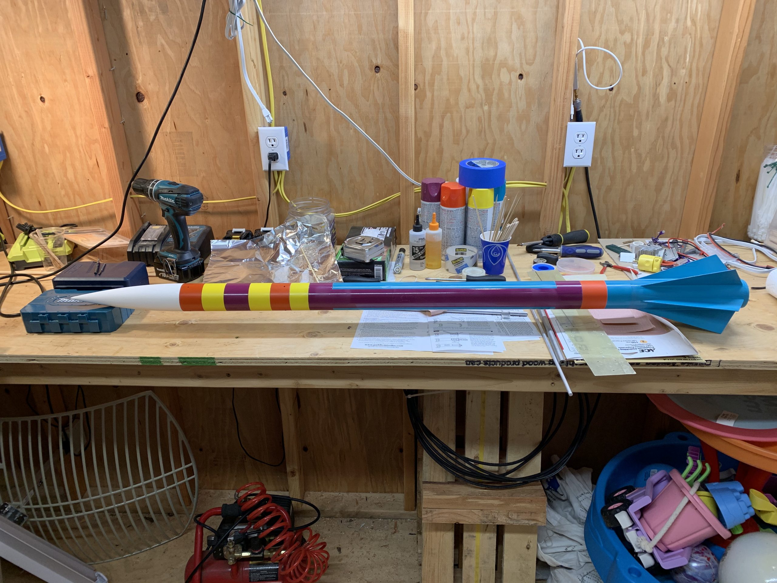
I finally decided after all these years helping out, that I would finally get my NAR L1 certification, so I picked up a kit and assembled it for a basic cert flight.
I also took it as an opportunity to put together a new custom flight board, this revision mostly for testing and gathering data, not actually controlling any chutes.
The first flight for my L1 cert was successful, and was recovered.
At that point, I had the telemetry data from the flight board from the first flight, and had achieved a good cert flight, so I put a bit peppier motor in for a second flight.
Unfortunately, a larger chute and a breeze carried it far enough that I was unable to recover it. I left a note with the local club, and maybe one of the local farmers will find it and turn it in. Otherwise it served the purpose, and I don’t feel too bad about losing it.
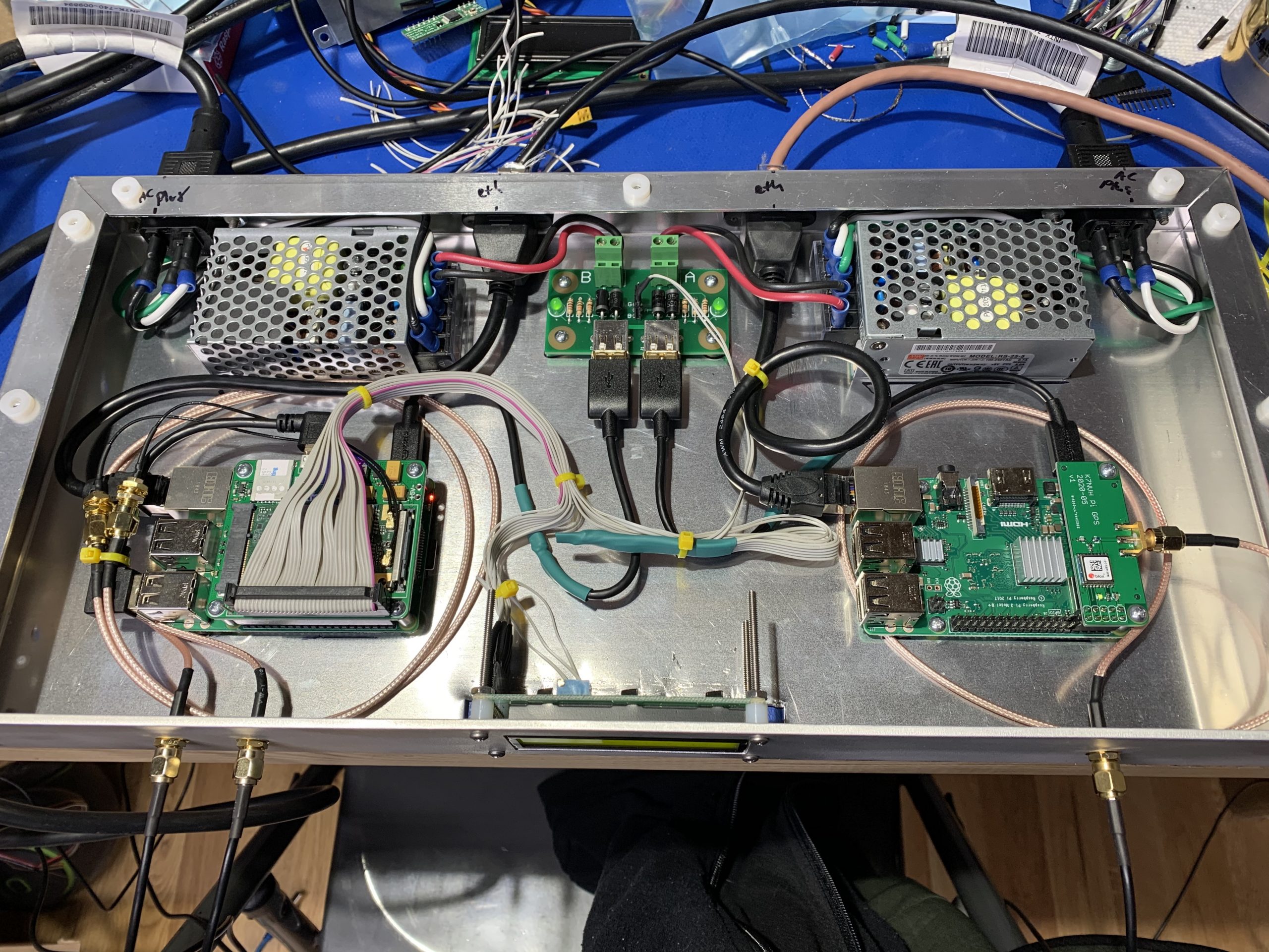
I have a rack of gear down at a datacenter down in California, where I’ve got a single internet connection. It’s quite reliable and performs well, but I wanted a backup means to reach my equipment in the case of an outage, or in the potential case of a router misconfig that breaks external connectivity.
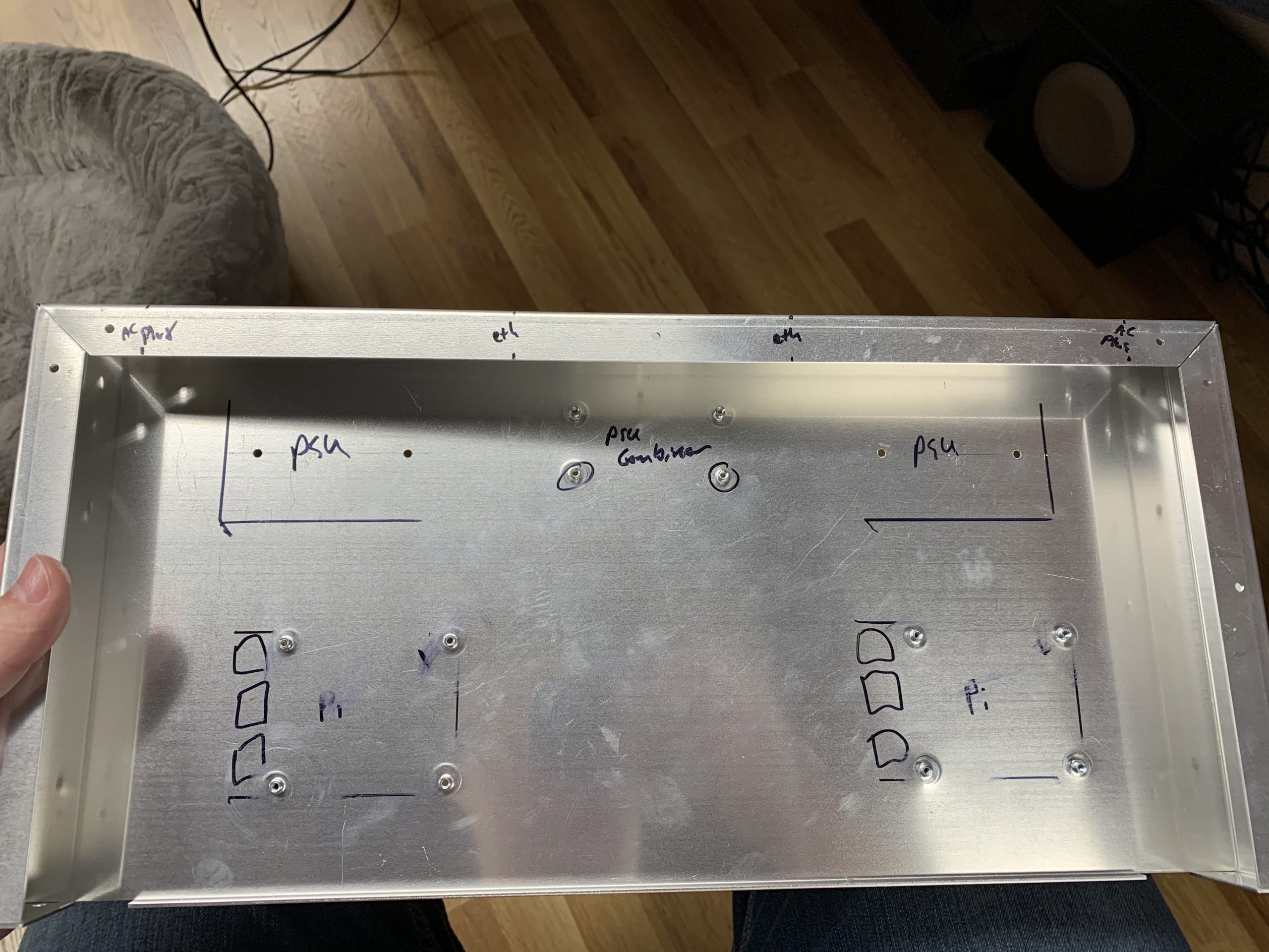
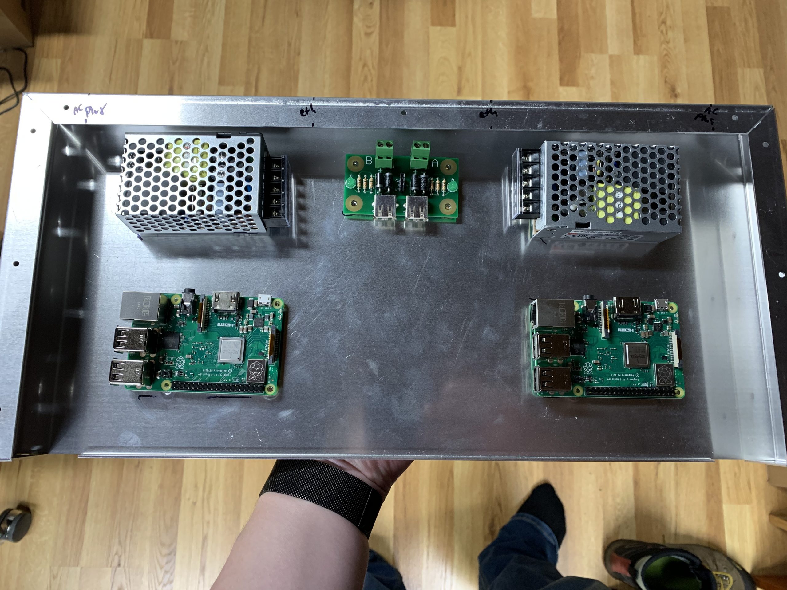
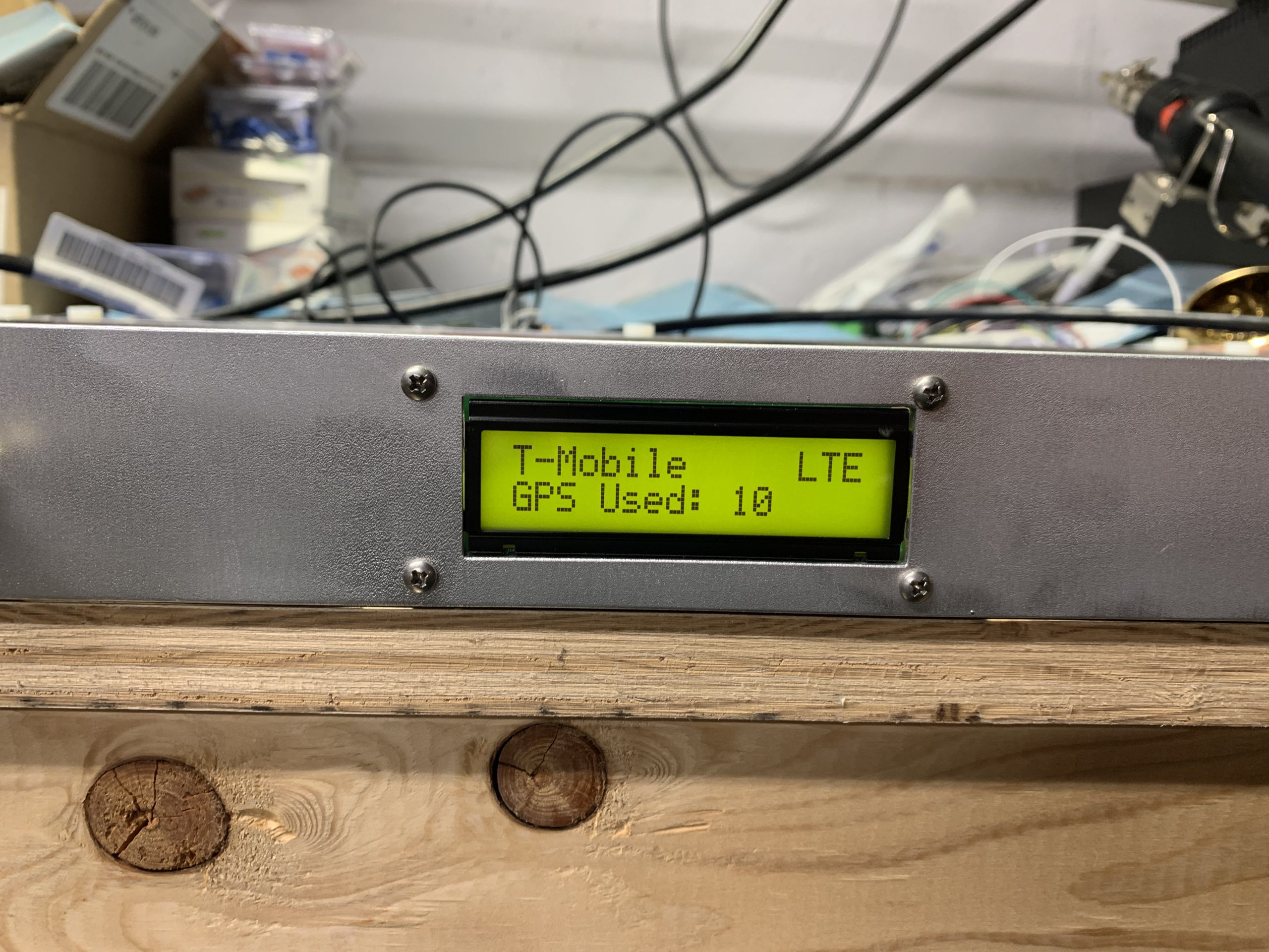
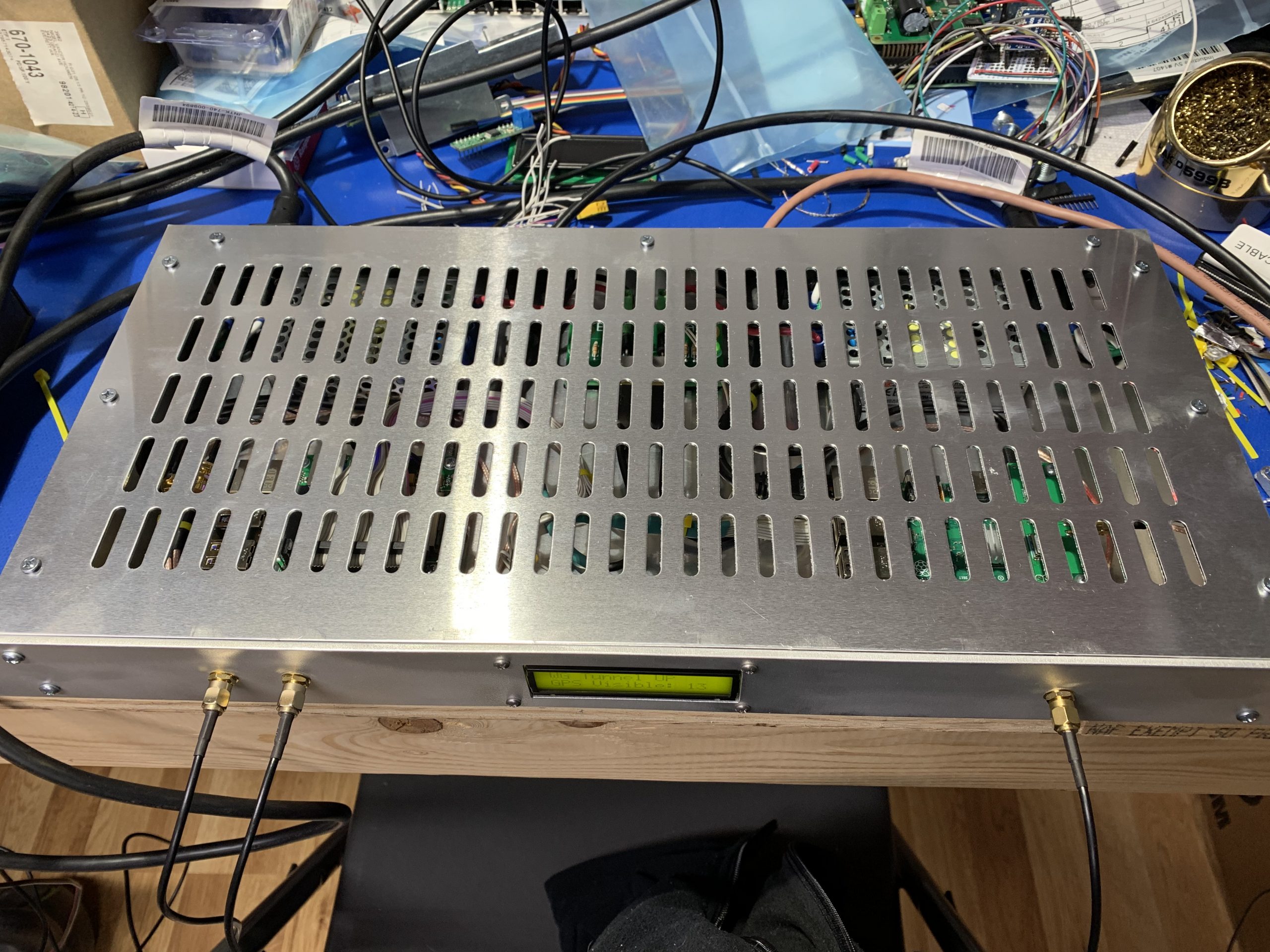
I had an extra 1U rackmount case from the PoE PDU project, and with the LTE modems I’ve been using for the Cellular Webcams, it seemed very reasonable to put something together and have an inexpensive Out of Band connection to my remote installation.
At the same time, I had plenty of room in the case for another Raspberry Pi, and another person who has gear in the same facility noted that *some* GPS signal was available inside, though perhaps not great, so I searched for a reasonably high gain GPS antenna, and decided to add a NTP Stratum 1 time server as well.
I designed a couple of very basic custom PCBs, one to combine the two power supplies to provide redundancy, and the GPS board for the Stratum 1 Pi. Added a basic character LCD I had laying around in the junk pile to provide visible status.
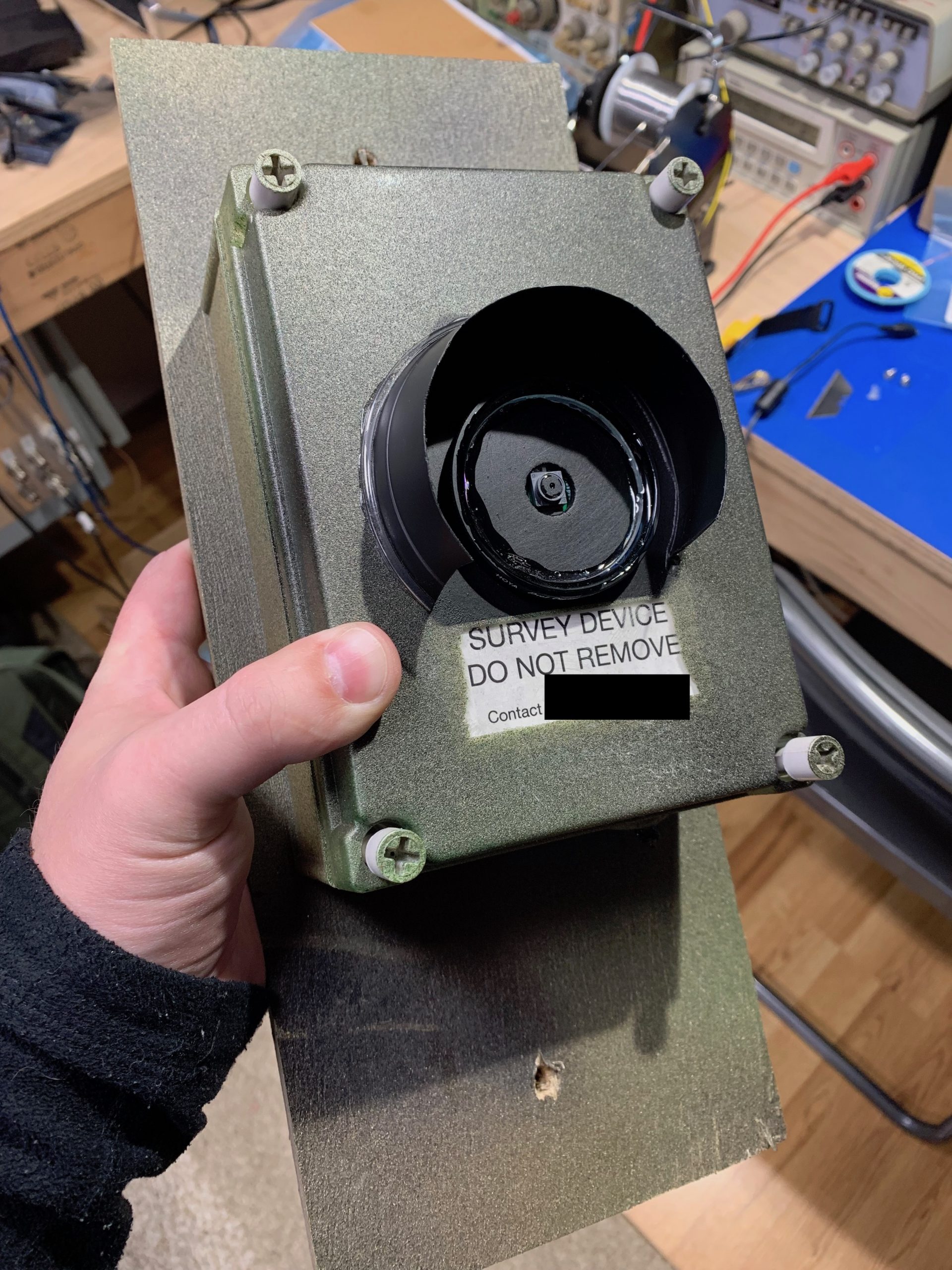
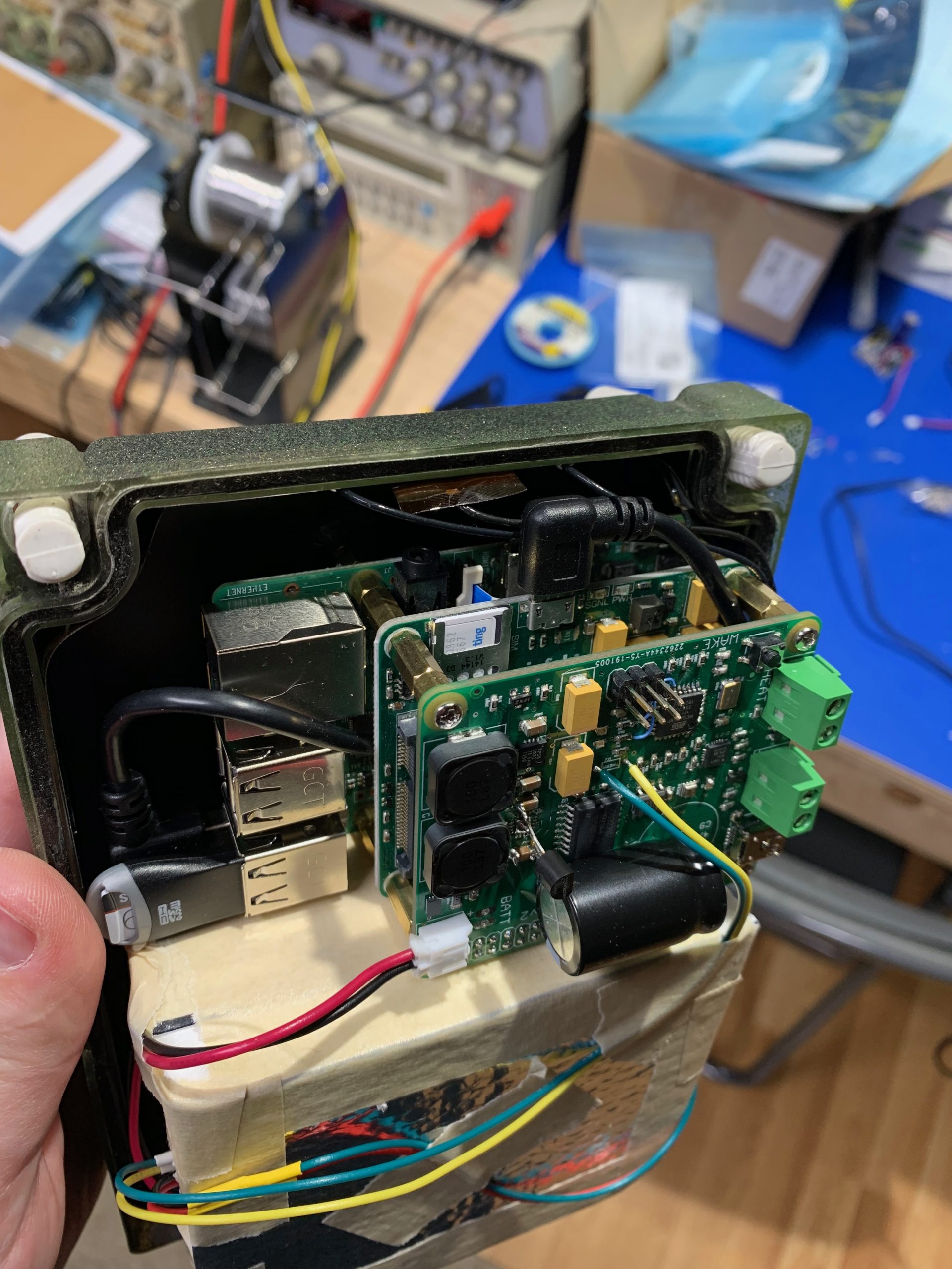
A couple years ago as I was first investigating IoT plans from various cell carriers, I threw together a small Raspberry Pi based remote webcam and left it in the woods over winter. It worked well for several months, and then died due to an SD card failure in the Pi. The lessons learned, as well as a few improvements I had been thinking on have come together into version two.
A higher quality, more robust SD card was chosen for the Pi, and the main filesystem was made read-only to reduce chances of failure. An USB stick was attached to store the images separate from the boot OS to keep the write activity separate. A new LTE capable cell modem was selected to improve performance and potentially give better coverage with most focus these days on LTE networks rather than the older 3G networks. Finally, a custom control board was designed and built which handles MPPT (approximation) solar charging, battery management, timekeeping and alarms to wake the Pi on schedule, several environmental sensors, and finally the power regulation to run the Pi and cell modem from a LiPo battery.
It is currently surviving the winter at ~4000′ elevation on a mountain top, and is working extremely well. Future improvements will bring cost reduction so I can deploy more of them, and potentially some feature enhancements like infrared capabilities to capture photos at night, which I’ve found is often when significant weather events happen, and would be interesting to see.
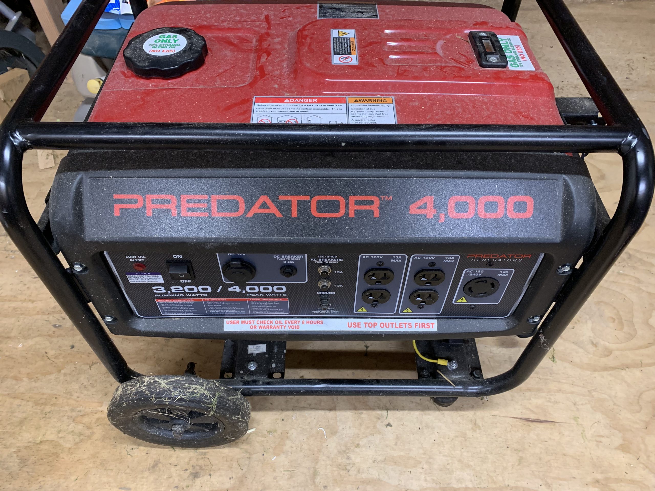
I’ve had a cheap Predator generator from Harbor Freight for a few years now. They’re cheap, and handy to have for camping/remote projects like Black Rock, or more locally, keeping the lights on, furnace blowing, and fridge cold if the power goes out at home.
Traditionally, these sorts of inexpensive generators operate on gasoline, which is easy, energy dense, and portable. However, there are downsides to relying on gasoline for backup or infrequent operations. Gas going bad, gathering water, clogging up the carburetor are all day ruining potentials when you’re trying to rely on the system when things have already failed, or there are no other options.
This leaves you in the endless dance of putting fuel stabilizer in, running the engine regularly, making sure that the gas hasn’t gotten too old because you don’t burn very much at a time, choreographing the generator shutdown to eliminate or reduce the amount of gas left in the carburetor.
Fortunately there are other fuels that don’t have the storage/fouling problems, and can with a little bit of adaptation, run in a conventional engine. In this case, we’re talking about propane and natural gas. Propane is easy to find at your local hardware store and many gas stations, you probably already have some for your barbecue grill, and potentially have a larger tank at your house for heating or cooking use already. Natural Gas comes to your home (if you have it), piped underground in effectively unlimited supply, irrespective of whether the hardware store is open, or the power is out. Natural Gas isn’t quite the portable option that Propane is, and is likely a bit harder to tap into your home’s Natural Gas piping, if you have a fixed backup generator, it’s a great potential.
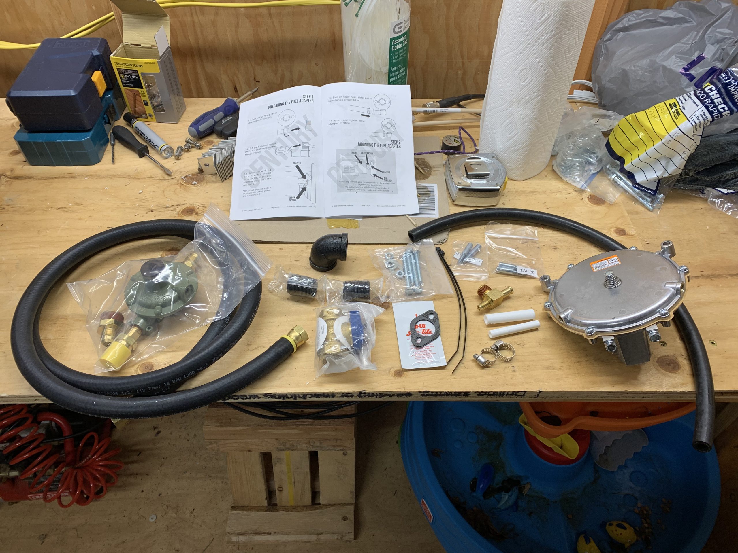
I found a simple kit which adds Propane and Natural Gas capability to my generator, while maintaining the option to use Gasoline. This very much appealed to me as I could still use gasoline if I took the generator portable down to Black Rock or elsewhere, but most of the time at home use Propane for backup services and avoid having the generator sit full of gas waiting to go bad. It also left using my home’s Natural Gas service as an option, though it’s not high on my priority list.
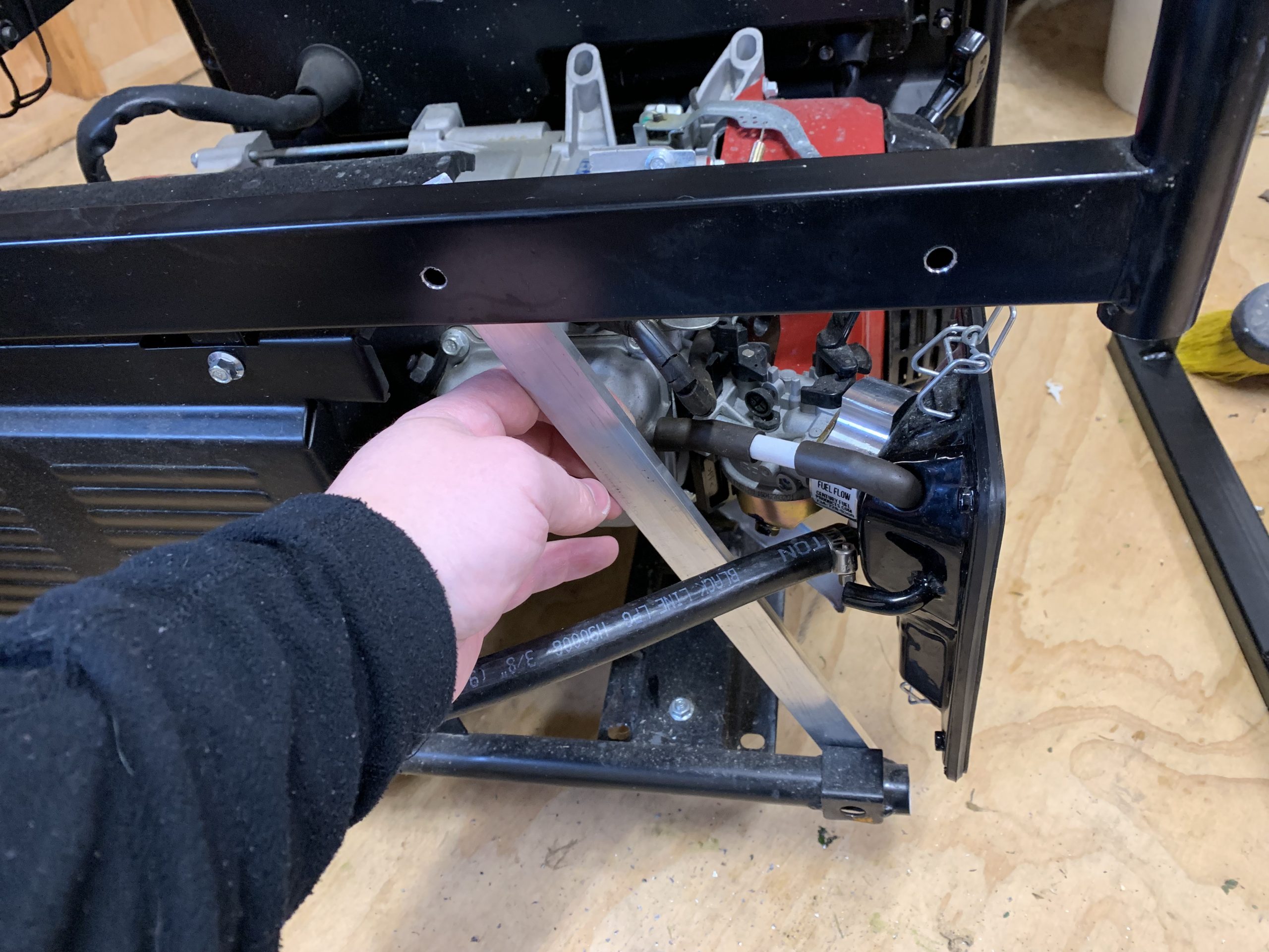
The kit comes with all the various bits needed for the conversion, though some tools, and a spare bit of scrap metal were required. In the case of my particular model of generator, some frame modifications were also necessary.
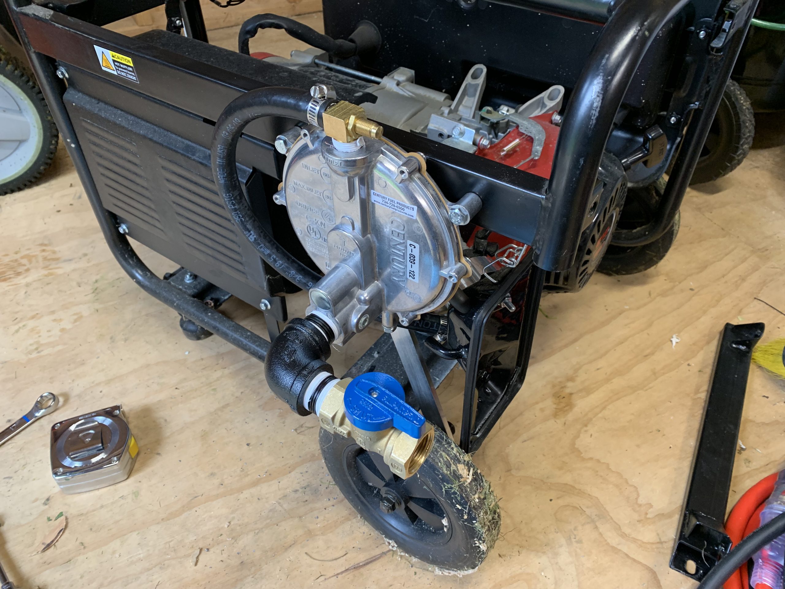
The conversion involves placing an extra block for the mixed gasses to enter the carburetor between the carb and the air box. Because of the design of my generator, this pushes the air box out into where the frame would be, requiring cutting away some of the frame, and reinforcing with a bit of scrap metal. Finally adding the regulator and small bit of plumbing completes the conversion.
A small bit of tuning the fuel mix after install to get it running well, and now I’ve got a generator I can leave worry free, and know it won’t be clogged up, or full of bad gas next time the power goes out.
A local friend recently was doing some work upgrading some solar panels at a remote site he has, and offered me the older panels that weren’t optimized for his setup. I decided I’d pick them up and mount them on the shed to form a better, more permanent installation than I had previously, with a few random panels effectively just sitting in the yard.
They are slightly mismatched, but all 12V style panels, so close enough to work for my small needs. I replaced the cabling, and wired them all in series. With open circuit voltage on “12V” panels being ~21V, the six in series could generate about 126VDC. Fortunately I have a charge controller capable of handling that (TriStar MPPT-30). That feeds into a 100Ah lead acid deep cycle battery, and powers an inverter for some lights when required, and a small buck converter to run a Raspberry Pi out in the shed.
Overall the system is about 700W of total panels, by no means ideally placed or angled, so real generation is a fair bit less, but it’s enough for the very modest use I need in the shed, and it’s nice not to have to run an extension cord to run the lights for a few. I’d still like to add a bit more battery capacity, minimizing depth of discharge on lead acid batteries very much limits actual usage, but that can come later.
Mounting was accomplished with two ‘vertical’ rails of unistrut in the same direction as the ribs in the metal roofing, and then four horizontal unistrut rails to actually attach the panels to. A standard weather head from the hardware store brings the cables inside neatly.