In the past I’ve posted about my experiments in receiving the image broadcasts from the POES polar orbiting weather satellites. These satellites are an interesting resource and have had a low barrier to entry for a long time, being able to use mostly conventional antennas and receivers with minimal or no extra hardware required.
They’re a great resource for getting local-ish, low to medium resolution imagery. However as they’re in polar orbits, they also come with a few drawbacks. You can only ever get images of where you are, they’re not always overhead, and getting good imagery at low elevation angles can sometimes require expensive azimuth-elevation rotators to track the moving satellite, or complex antenna designs.
Since the time of playing with these satellites, I’ve had an interest rolling around in the back of my head to try picking up the GOES series geostationary satellites. These satellites take full disk images of the earth at high resolution, and sit at a fixed position in the sky. However they require non-typical antennas, preamplifiers and filters, and a receiver capable of taking in a bit more than 1.2MHz of bandwidth at 1694.1MHz.
Fortunately recent years, and some clever folks, have brought these items into easy and inexpensive accessibility. As such I’ve set up a receiver station. Here’s the setup I’m using to receive photos like this one off the air.
Antenna
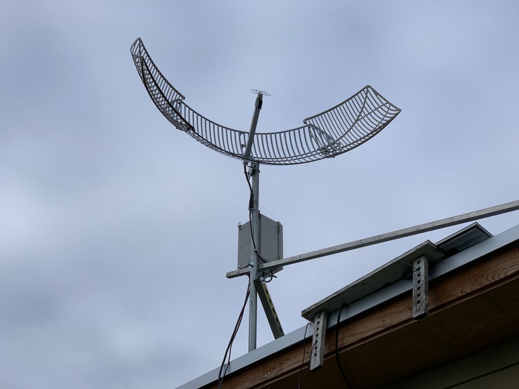
First let’s touch on the antenna. A high gain antenna with an operating frequency around 1.7GHz is going to be required. I’ve seen reports that a 1 meter parabolic dish is considered the minimum, which I’ve confirmed does work for my testing. However to get improved signal quality a larger dish is desirable. It’s a bit cobbled together, but my current dish is probably in the range of 1.5 meters.
Very few commercial dishes are available currently in this frequency range. There are a number of references to an L-Com branded dish working in various other write ups on this topic, however that dish appears to be unavailable at this point. The alternatives I’ve found are this 1.7GHz dish that as of this time still seems to be available. Or modifying a readily available 2.4GHz wifi dish like this one.
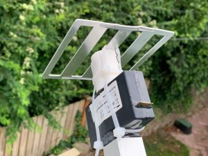
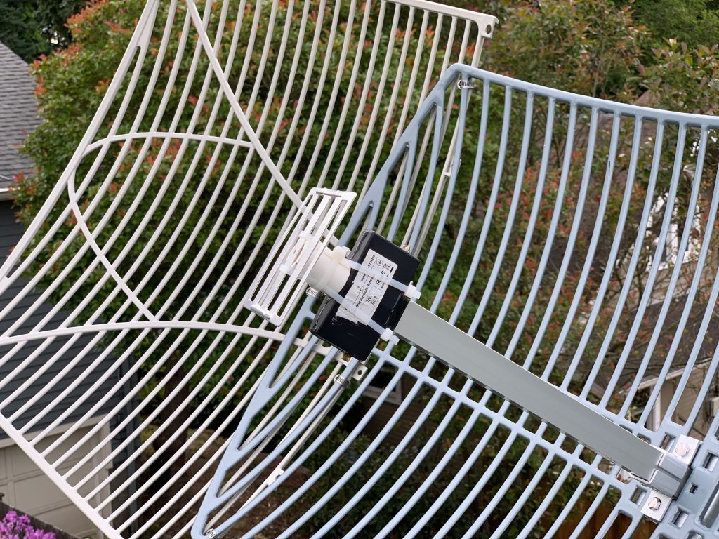
The commercial 1.7 GHz dish can be used out of the box. The 2.4GHz wifi dish will need some slight modifications. Others have posted modifications of bending the subreflector to be more shallow, which in my case I have found to be best at nearly flat. The second modification is to use a small bit of PVC pipe to extend the subreflector out approximately one inch, which I have also found as an improvement. The third modification I completed which may not be strictly necessary, but seems to help in my case, was to cut open the black plastic antenna housing, and extend the dipole legs to match a 1.7GHz frequency. Other reports on using this antenna have had success without making this modification, so I would not consider it a hard requirement. You can see these modifications in this photo.
As noted above, I have also cobbled the antenna a bit to extend the parabola to get more gain from the antenna. I used some additional grid dish sections from another unused antenna, and attached them with hose clamps. See here.
Pointing the antenna is quite critical. A very small deviation in aim will dramatically impact signal. It’s important to get the rough aim set with a compass and angle gauge, then fine tune by adjusting tiny increments while watching the reported signal values. Tools like https://www.dishpointer.com/ will help you get approximately pointed. In my case I’m aimed at GOES West, which is at 137.2 West.
Preamplifier & Filter
The next step in the RF chain is something to filter out unwanted noise and boost the desired signal levels. Fortunately this step is an easy one. NooElec, a supplier of a number of SDR related gizmos have custom made a preamp and filter gadget specifically for this purpose at a hobby friendly price. Check out the SAWbird+ GOES.
Software Defined Radio
The final step in our RF chain will be the SDR receiver. These are commonplace these days in the hobby and can be had inexpensively. However not all are created equal. On the SAWbird+ GOES page, they reference this receiver, and I believe it should work and others have had luck with it. Perhaps I got a bad one, but I was unable to get it to perform well. I have ended up using this receiver, which is a bit cheaper and seems to work well in my case.
Computer
Obviously, the SDR will need a computer to plug into. Just about any will do, and a number of folks (including myself) use a Raspberry Pi board for this task. I would recommend at minimum the model 3B+, but would suggest the Raspberry Pi 4 to make sure you have enough CPU power, as the SDR is rather CPU intensive.
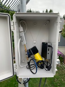
The SAWbird+ Goes, SDR, and Raspberry Pi all got installed in a weatherproof enclosure near the antenna to minimize signal losses in the cabling.
Software
Finally comes the software you run on the computer, which listens to the SDR, and decodes the signals, and processes them into images. There are some commercial software suites available for this, but I have used an open source setup called goestools. I’m not going to rehash their guides on compiling and installing, as they’ve got reasonable guides available. I will note some ‘gotchas’ I have run into.
The software is split into two utilities you’ll use in concert. ‘goesrecv’ actually listens to the SDR and decodes the RF into data packets. ‘goesproc’ will take in those data packets and process them into images and text files as relevant.
I have found goesrecv does not report when there isn’t enough CPU power and it ends up dropping samples from the SDR. This issue ends up presenting like goesrecv reports poor signal. A particular signature I saw is that signal numbers would be good for a second or two, and then go bad as it wasn’t able to keep up. I’m not certain that signature is universally applicable, but it showed up for me. I addressed this issue by making sure I had a reasonably powerful Pi, and setting the sample_rate parameter in the configuration file lower. You can’t go too low until you start cutting out the signal itself. I have mine set to ‘sample_rate = 1300000’.
The gain parameter for goesrecv is also critical. You’ll need to find a value that works best for your particular setup. I suspect the typical will be around ‘gain = 30’, but trying values between 0 and 50, and then seeing what the signal values look like will tell you where yours needs to be.
Options for goesproc are significantly less fiddly, and mostly consist of what images you want saved and where. My configuration is largely based on this example from the repo.


