GOES West HRIT Reciever

In the past I’ve posted about my experiments in receiving the image broadcasts from the POES polar orbiting weather satellites. These satellites are an interesting resource and have had a low barrier to entry for a long time, being able to use mostly conventional antennas and receivers with minimal or no extra hardware required.

They’re a great resource for getting local-ish, low to medium resolution imagery. However as they’re in polar orbits, they also come with a few drawbacks. You can only ever get images of where you are, they’re not always overhead, and getting good imagery at low elevation angles can sometimes require expensive azimuth-elevation rotators to track the moving satellite, or complex antenna designs.

Since the time of playing with these satellites, I’ve had an interest rolling around in the back of my head to try picking up the GOES series geostationary satellites. These satellites take full disk images of the earth at high resolution, and sit at a fixed position in the sky. However they require non-typical antennas, preamplifiers and filters, and a receiver capable of taking in a bit more than 1.2MHz of bandwidth at 1694.1MHz.

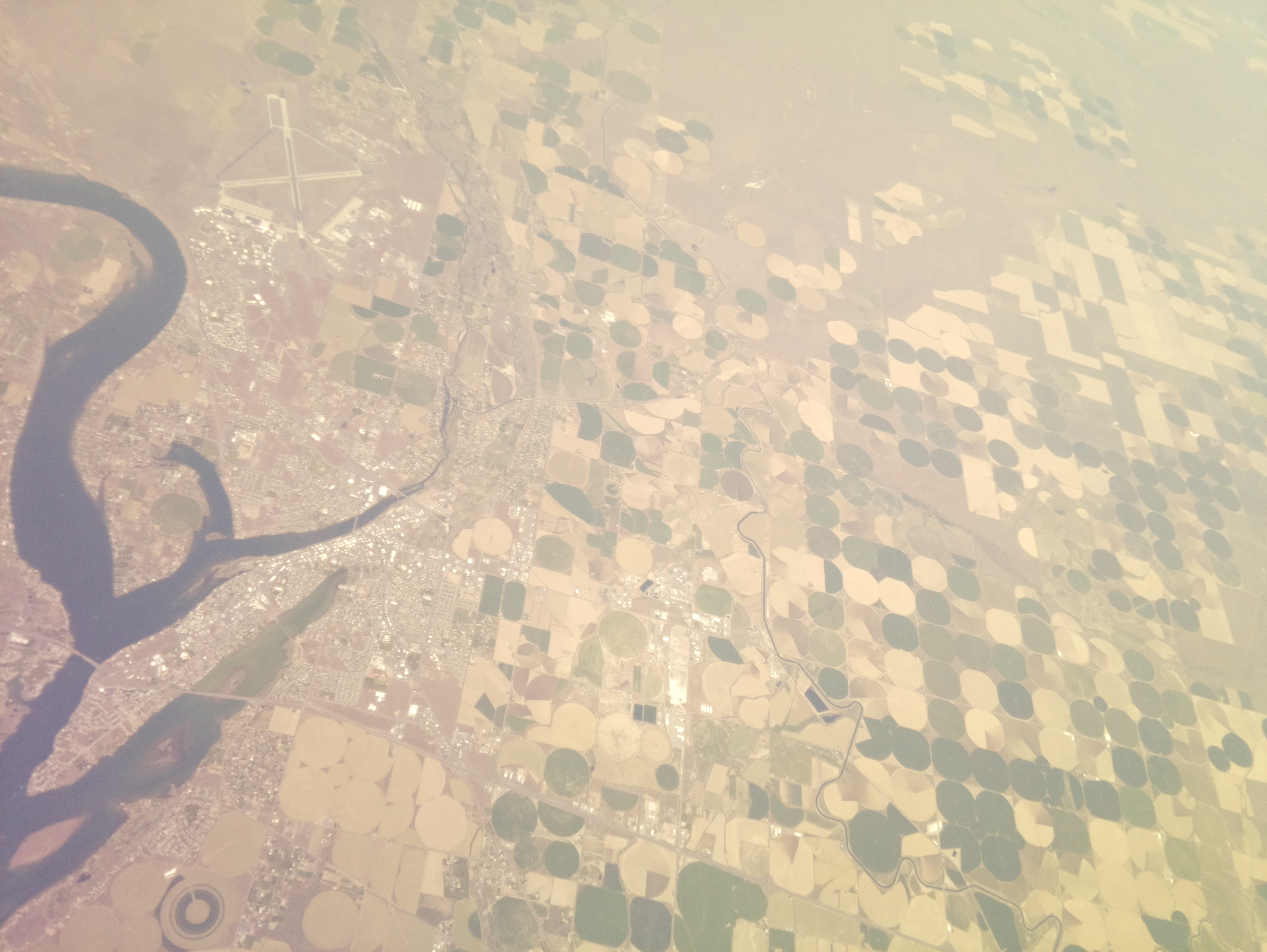
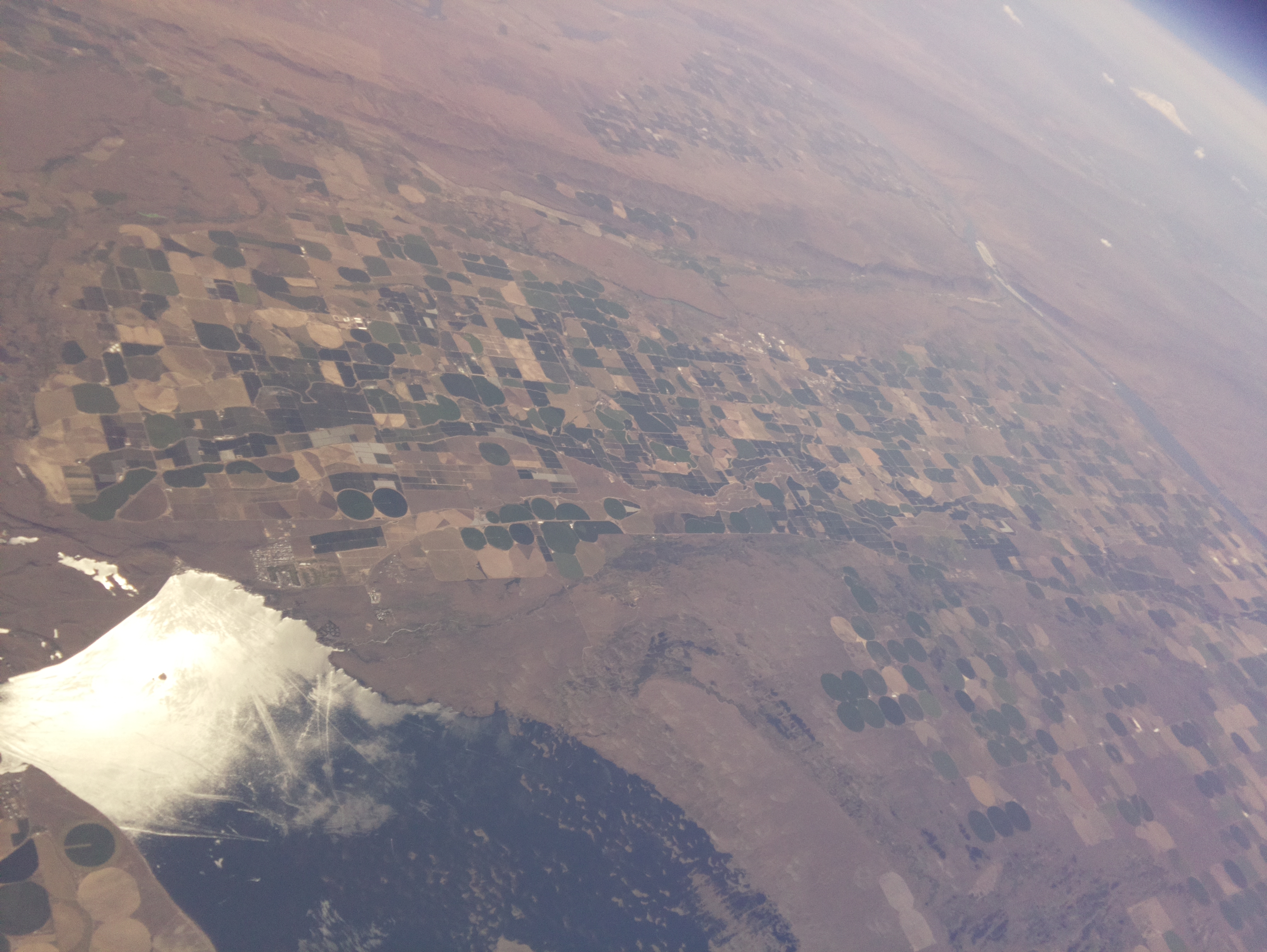
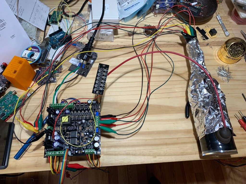
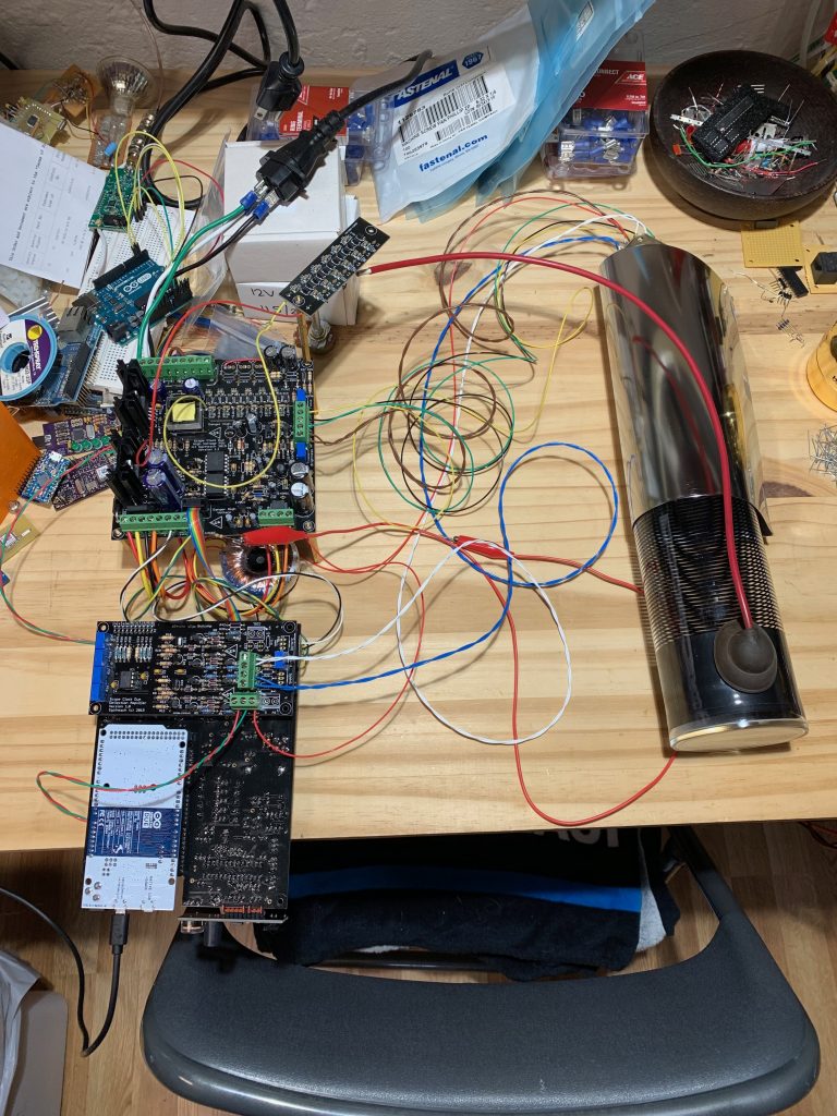
Fortunately recent years, and some clever folks, have brought these items into easy and inexpensive accessibility. As such I’ve set up a receiver station. Here’s the setup I’m using to receive photos like this one off the air.

Antenna
First let’s touch on the antenna. A high gain antenna with an operating frequency around 1.7GHz is going to be required. I’ve seen reports that a 1 meter parabolic dish is considered the minimum, which I’ve confirmed does work for my testing. However to get improved signal quality a larger dish is desirable. It’s a bit cobbled together, but my current dish is probably in the range of 1.5 meters.

Very few commercial dishes are available currently in this frequency range. There are a number of references to an L-Com branded dish working in various other write ups on this topic, however that dish appears to be unavailable at this point. The alternatives I’ve found are this 1.7GHz dish that as of this time still seems to be available. Or modifying a readily available 2.4GHz wifi dish like this one.

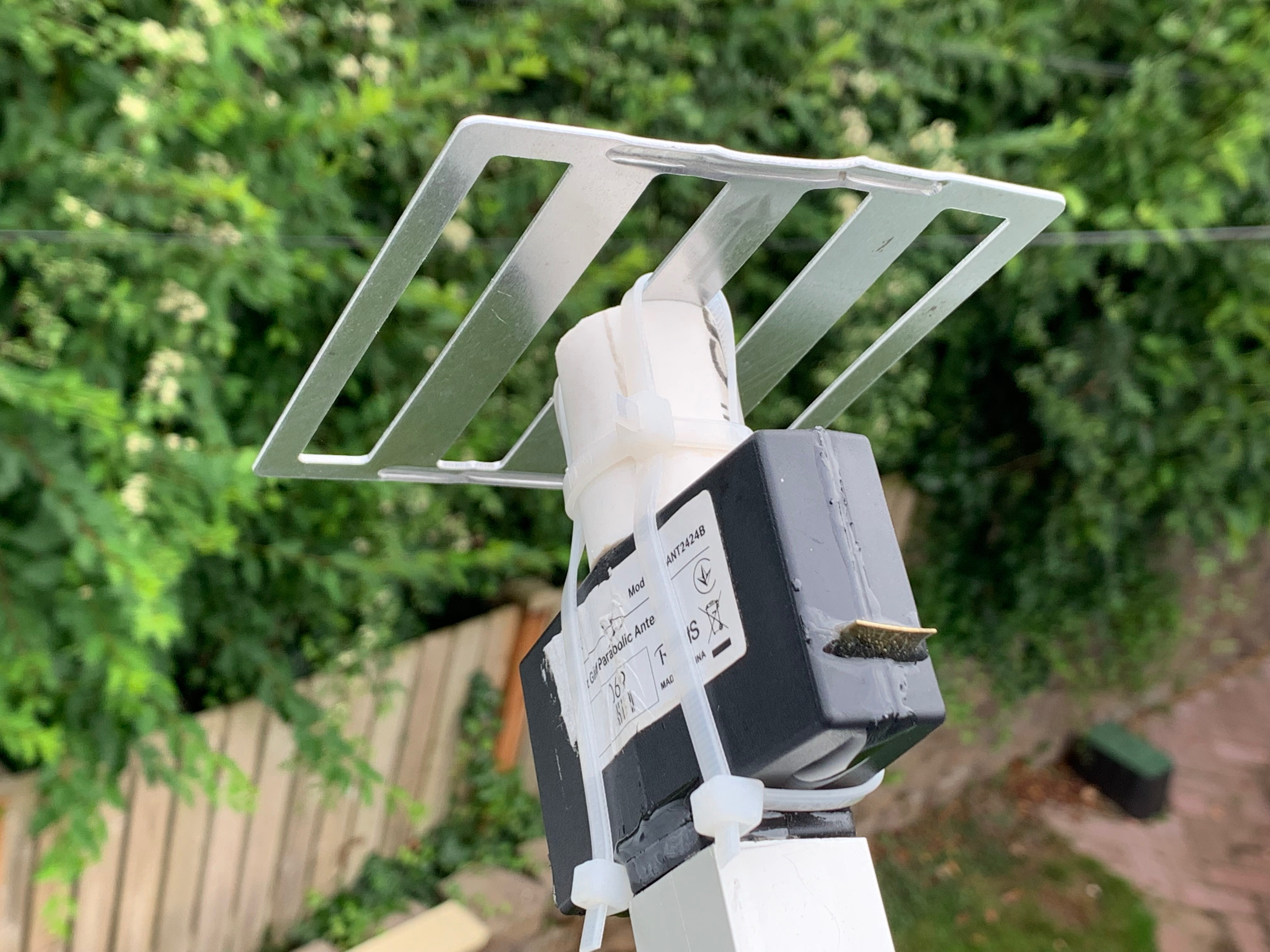
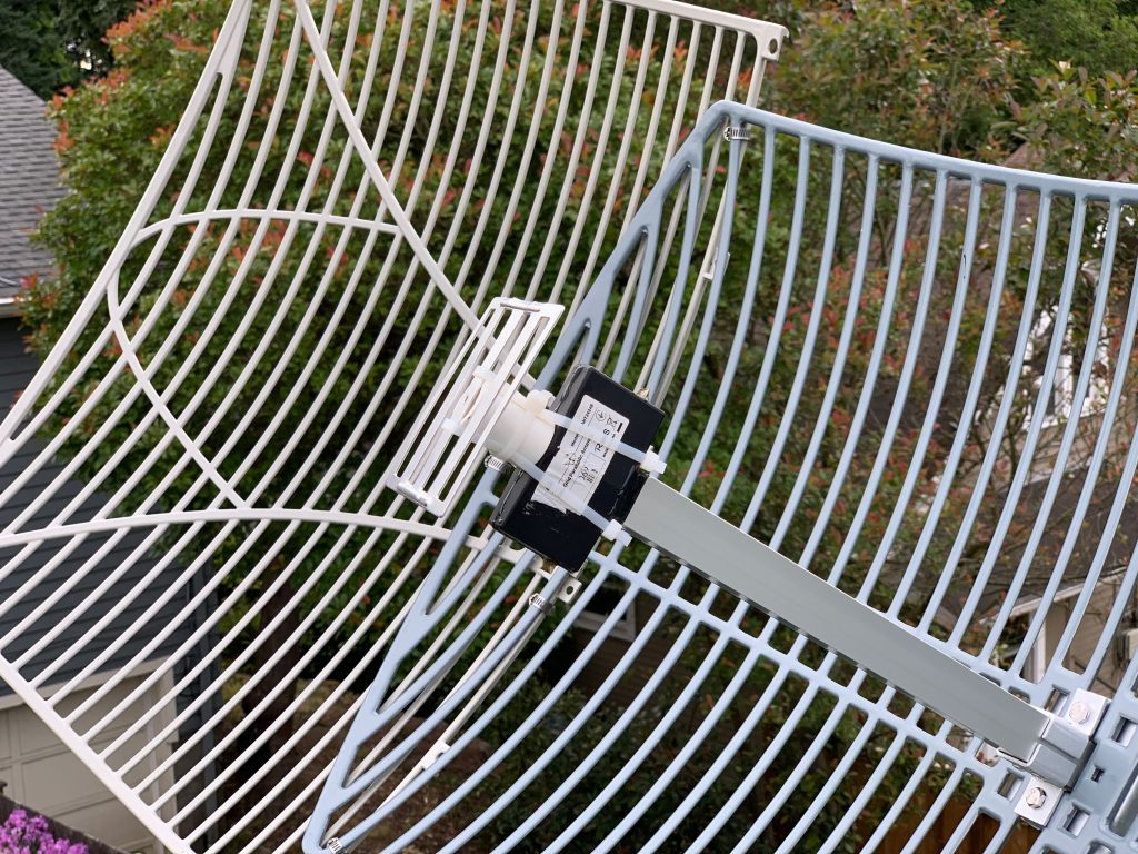
The commercial 1.7 GHz dish can be used out of the box. The 2.4GHz wifi dish will need some slight modifications. Others have posted modifications of bending the subreflector to be more shallow, which in my case I have found to be best at nearly flat. The second modification is to use a small bit of PVC pipe to extend the subreflector out approximately one inch, which I have also found as an improvement. The third modification I completed which may not be strictly necessary, but seems to help in my case, was to cut open the black plastic antenna housing, and extend the dipole legs to match a 1.7GHz frequency. Other reports on using this antenna have had success without making this modification, so I would not consider it a hard requirement. You can see these modifications in this photo.

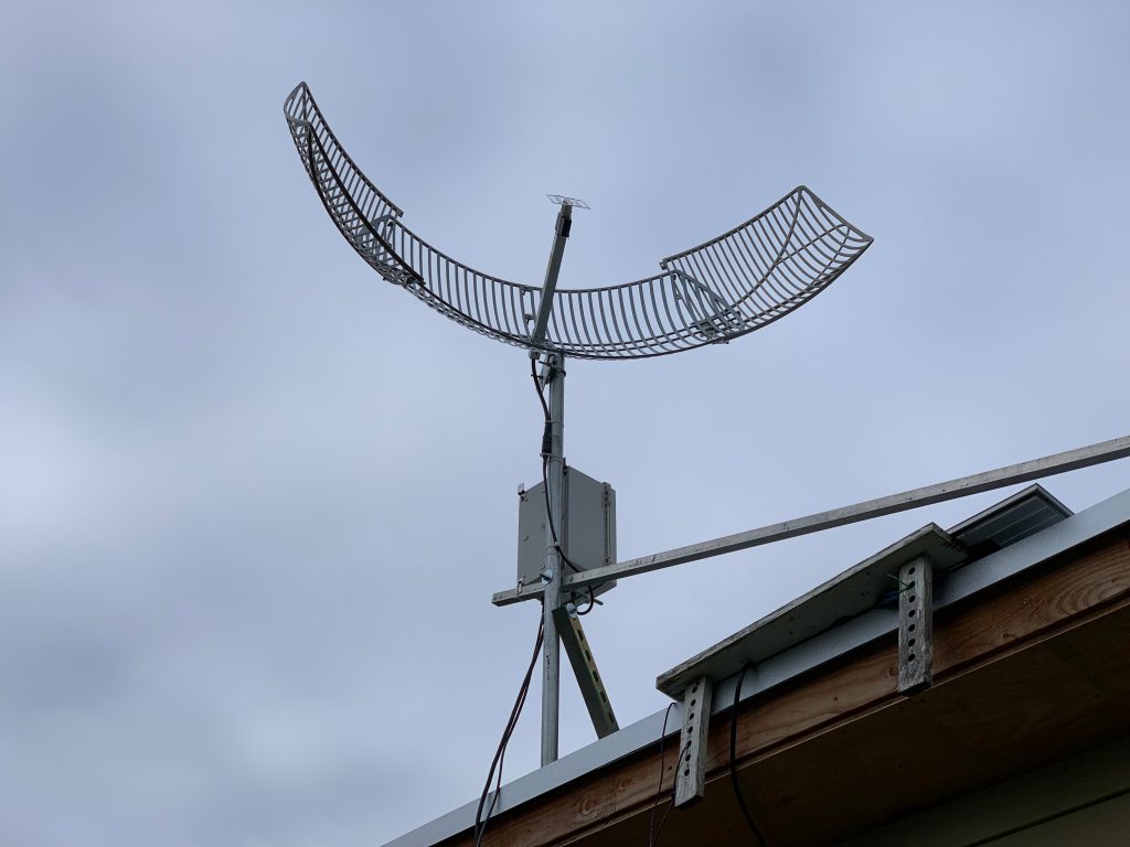
As noted above, I have also cobbled the antenna a bit to extend the parabola to get more gain from the antenna. I used some additional grid dish sections from another unused antenna, and attached them with hose clamps. See here.

Pointing the antenna is quite critical. A very small deviation in aim will dramatically impact signal. It’s important to get the rough aim set with a compass and angle gauge, then fine tune by adjusting tiny increments while watching the reported signal values. Tools like https://www.dishpointer.com/ will help you get approximately pointed. In my case I’m aimed at GOES West, which is at 137.2 West.

Preamplifier & Filter
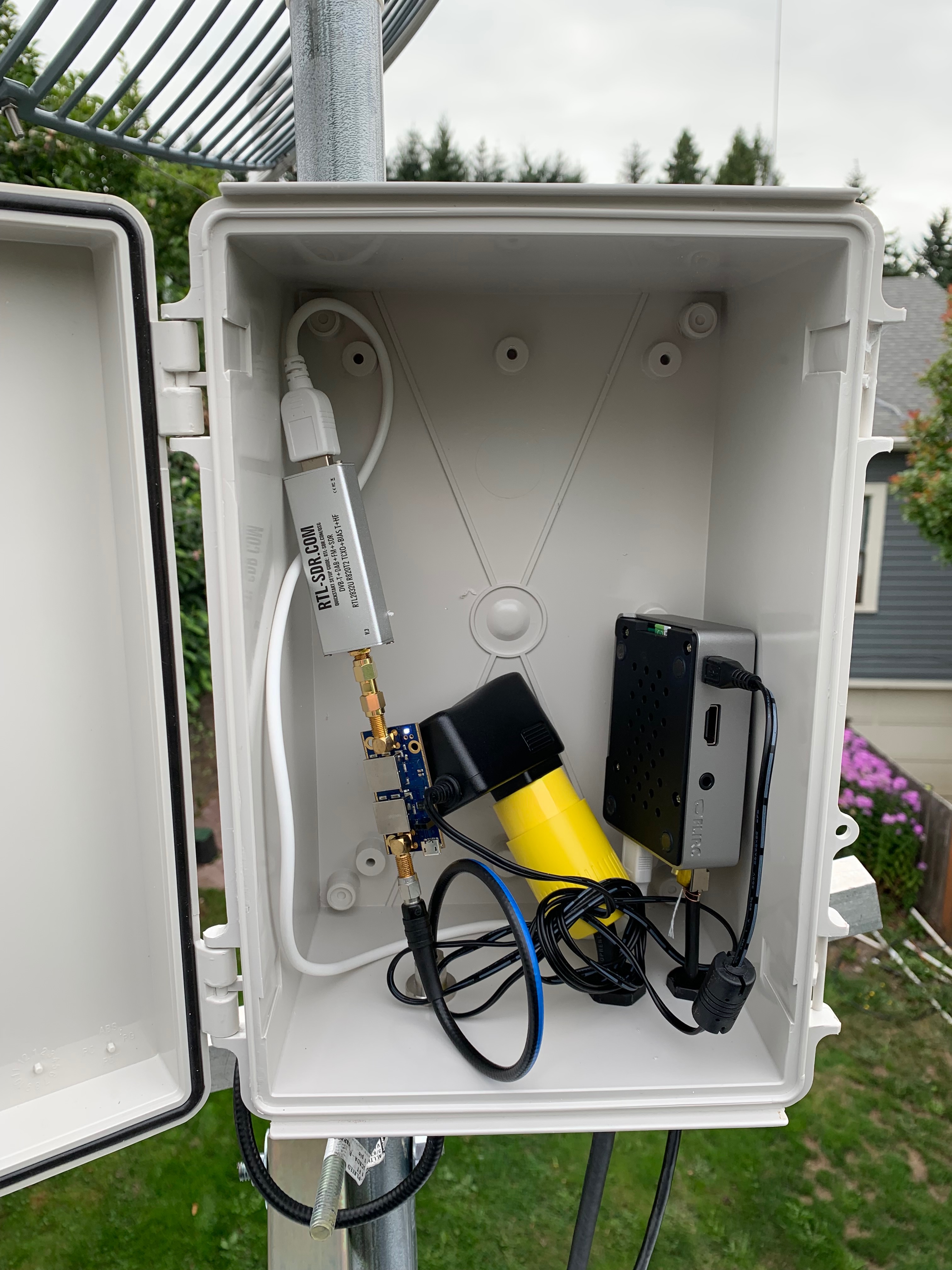
The next step in the RF chain is something to filter out unwanted noise and boost the desired signal levels. Fortunately this step is an easy one. NooElec, a supplier of a number of SDR related gizmos have custom made a preamp and filter gadget specifically for this purpose at a hobby friendly price. Check out the SAWbird+ GOES.

Software Defined Radio
The final step in our RF chain will be the SDR receiver. These are commonplace these days in the hobby and can be had inexpensively. However not all are created equal. On the SAWbird+ GOES page, they reference this receiver, and I believe it should work and others have had luck with it. Perhaps I got a bad one, but I was unable to get it to perform well. I have ended up using this receiver, which is a bit cheaper and seems to work well in my case.

Computer
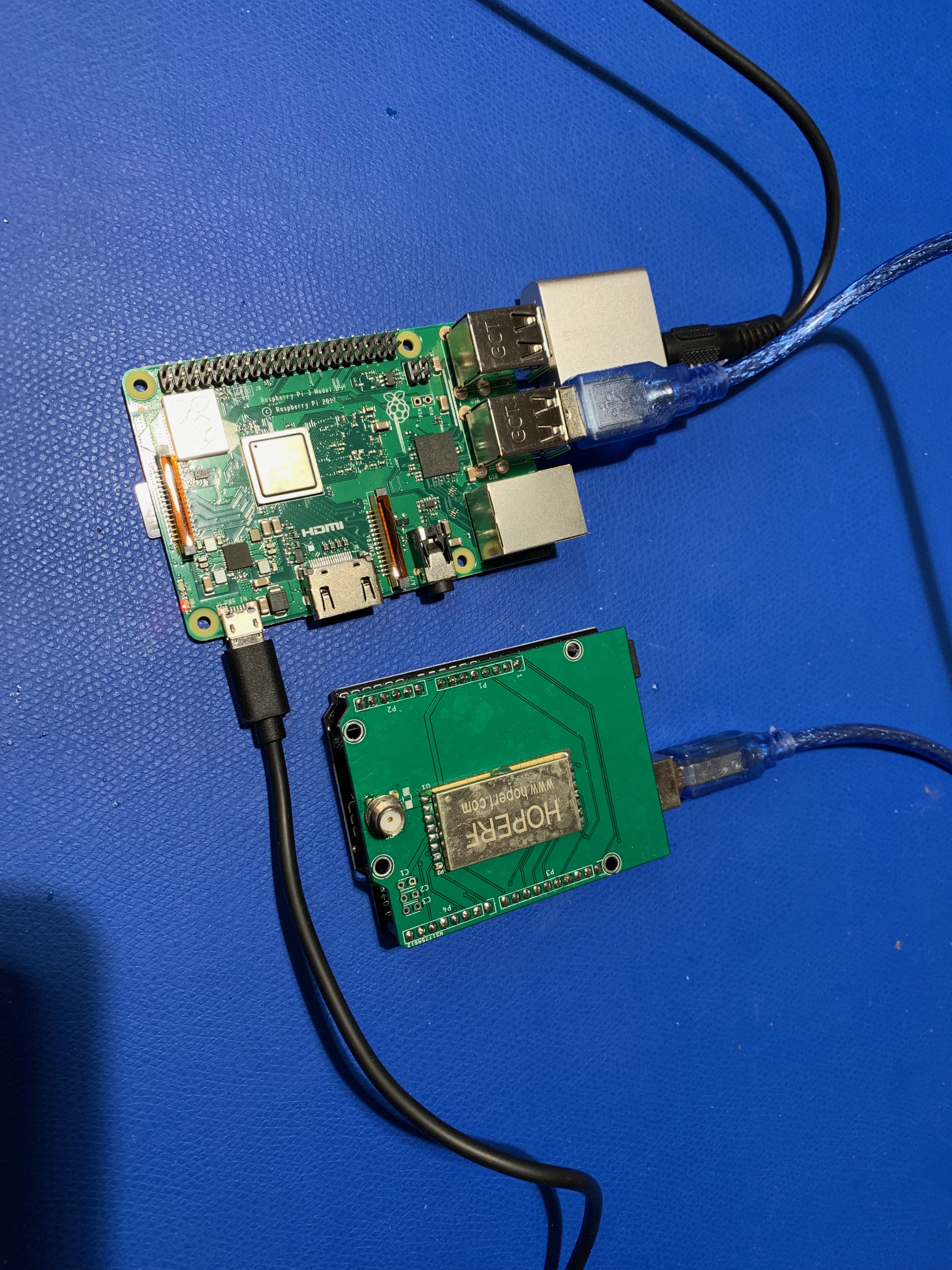
Obviously, the SDR will need a computer to plug into. Just about any will do, and a number of folks (including myself) use a Raspberry Pi board for this task. I would recommend at minimum the model 3B+, but would suggest the Raspberry Pi 4 to make sure you have enough CPU power, as the SDR is rather CPU intensive.

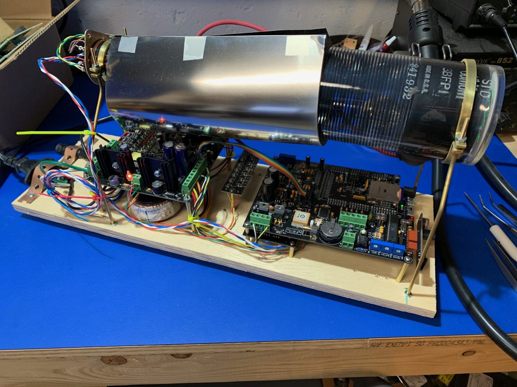
The SAWbird+ Goes, SDR, and Raspberry Pi all got installed in a weatherproof enclosure near the antenna to minimize signal losses in the cabling.

Software
Finally comes the software you run on the computer, which listens to the SDR, and decodes the signals, and processes them into images. There are some commercial software suites available for this, but I have used an open source setup called goestools. I’m not going to rehash their guides on compiling and installing, as they’ve got reasonable guides available. I will note some ‘gotchas’ I have run into.

The software is split into two utilities you’ll use in concert. ‘goesrecv’ actually listens to the SDR and decodes the RF into data packets. ‘goesproc’ will take in those data packets and process them into images and text files as relevant.

I have found goesrecv does not report when there isn’t enough CPU power and it ends up dropping samples from the SDR. This issue ends up presenting like goesrecv reports poor signal. A particular signature I saw is that signal numbers would be good for a second or two, and then go bad as it wasn’t able to keep up. I’m not certain that signature is universally applicable, but it showed up for me. I addressed this issue by making sure I had a reasonably powerful Pi, and setting the sample_rate parameter in the configuration file lower. You can’t go too low until you start cutting out the signal itself. I have mine set to ‘sample_rate = 1300000’.

The gain parameter for goesrecv is also critical. You’ll need to find a value that works best for your particular setup. I suspect the typical will be around ‘gain = 30’, but trying values between 0 and 50, and then seeing what the signal values look like will tell you where yours needs to be.

Options for goesproc are significantly less fiddly, and mostly consist of what images you want saved and where. My configuration is largely based on this example from the repo.

Posted in Uncategorized | Leave a comment

2019 Balloons Launch

2019’s launch included a single balloon which reached 101,433 feet. The flight carried carried a number of student payloads, the 900MHz voice telemetry system, a commercial APRS tracker board, my custom IRIS board, as well as a Raspberry Pi Zero W with a Camera V2 module, and a new experimental tracker based on the LoRa boards from Enhanced Radio Devices.

The APRS systems are our tried and true trackers, which consistently have provided solid performance for our flights, and got us a good position packet at about 2000′ above the ground during the descent which gives us a nice narrow search area, as it won’t drift very far during that time. In the case of this flight, final landing position was just a bit under 300 yards from that last airborne position. APRS has the advantage of having multiple listening stations, some of which are high up, which provides good coverage for packets we may not necessarily hear from the launch site. The downside is that other folks use APRS, and we have to share the channel, which means limiting the interval we transmit positions on.

The LoRa tracker was something I’ve been interested in trying to see how it compares with our traditional APRS systems, as I’ve heard success stories from folks I know in the UK doing balloon flights, and as it’s not a popular system like APRS, we can transmit more frequently without bothering others. In this case I set the transmit interval to about 15 seconds. It is possible to have multiple receivers, but it does not currently have the same built in benefit like APRS. If we wanted multiple, we would have to provide them ourselves. The module was set to 100mW transmit power, and configured for a slower data rate to improve signal strengths. A small 1/4 wave coaxial dipole on the payload, and a simple 5/8 wave whip on my vehicle were the antennas. Performance was beyond my expectations by a fair margin. The transmissions were quite robust through the whole flight, only missing a small handful of packets, and the last position received was about 600′ above the last APRS position, which had the help of additional dispersed receivers. It’s not hard to imagine with another receiver located ahead of time at the predicted landing area, we could have gotten an even lower position during the descent.

The Raspberry Pi and camera were configured to take a photo every 5 seconds, and performed well, returning some nice images during the flight. The only trouble was some hazy conditions from a nearby wildfire.

Posted in Electronics, Ham Radio, Projects, Technology | 2 Comments

Brothers 2019

The weather again chose not to cooperate this year for our regular venture down to Black Rock for the UW rocketry class. However instead of cancelling altogether, we were able to adjust our plans and visit a launch site in Brothers, OR. It was a shorter trip, just over a long weekend, but was neat to see a new area.

The group was again smaller this year because the late schedule put the trip into the next quarter’s classes, but still a decent turnout. A number of good flights were had, though recovery was hampered by the scrubland, in comparison to the perfectly flat and open playa we usually have at Black Rock.

Posted in Projects, Random | Leave a comment

LitePlacer Pick and Place

I end up doing a number of PCB designs for various projects. Most are small one offs that aren’t a huge problem to assemble by hand, but there are instances where I have multiple to build, or large boards with hundreds of components. In these cases it can take a number of hours of tedious, exacting, labor to place all the parts. Especially in the case of needing multiple, I found myself putting off the work and letting those projects languish.

In light of that, I decided to purchase an open source prototyping pick and place machine, specifically the LitePlacer. This machine comes as a kit, and after assembly and calibration, can place components on boards automatically. It’s not as fast as a professional production pick and place machine, but it also doesn’t cost a million dollars and I can set it up and let it run while I work on other things.

I found the kit instructions quite good, and quickly had the mechanical build completed.

Next was the electrical build which included wiring up all the motors, switches, and other bits to the control board. Then would be calibration and testing.

And finally, placement of the first board!

Since then I’ve placed a few much larger boards with hundreds of components, and I’m quite pleased with how the machine runs. I still need to do a bit of work in terms of the optical recognition on black and clear tapes, but overall I’m pleased to be able to offload this work a bit.

Posted in Electronics, Projects, Technology | 1 Comment

CRT Clock Build

While it’s not particularly new or novel, I’ve long been interested in setting up an Oscilloscope Clock with one of the various kits that have been available for some time. Over the holidays one of the gifts from my family was based on this, and encouraged me to go further to build a clock around a raw CRT tube, rather than just something that interfaces with an existing oscilloscope.

Soon enough I had found a real gem of a tube with a helical PDA, which I thought was just gorgeous.

The tube is a 3BFP1, which is a 3 inch, flat face, with a standard green phosphor like you’d see on an oscilloscope.

Next I needed a setup to drive the tube, which needs a number of various high voltage sources to drive it. I didn’t particularly feel like jumping into designing those circuits myself at the moment, so I found a kit from a fellow in the UK which handled the various power supply needs, and included a very smooth clock display board as well at http://www.sgitheach.org.uk/scope3.html

Soon enough the kit was in hand, and thus began a few evenings of soldering the kit together.

At this point I’ve got power to the tube, and first light. It’s still not well focused, but good progress. Next I move onto building the clock and signal amplifier boards, which will let me actually try displaying something on the tube.

Finally some more work on getting the voltages tweaked to improve brightness and focus, and I had a display I was happy with.

Not perfect, but there may also still be a little room for improvement when it all gets built into an enclosure when I add magnetic shielding. Next I started working on a prototype layout for all the components before I commit to things.

This is how it stands today. I think I’m happy with this layout, so now as I have the time, I’ll make a base out of some wood that’s a bit nicer than plywood, and work on an acrylic enclosure to keep fingers out of the high voltage bits, but still allow the tube to be on display.

Posted in Art, Electronics, Projects, Technology | Leave a comment