For the last few years I have off and on run a receiver dedicated to picking up the image transmissions from NOAA’s POES series of satellites.
The POES satellites are polar orbiting weather satellites that transmit image data down, and are available to anyone who cares to set up a station.
In the past, I have used a receiver I built as a kit, and it worked alright, but getting good performance out of it has been troublesome, so the images often had issues with noise, or not faithfully reproducing the actual data the satellites were sending.
I was working on getting my station tuned up again recently, and decided to try using a USB SDR (Software Defined Radio) attached to a Raspberry Pi, to see if I could get better results, and I have to say I’m pleased with the answer.
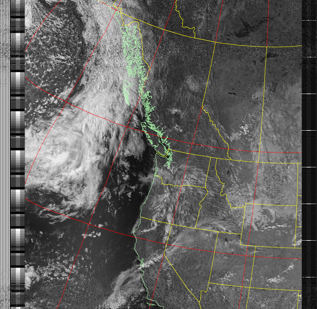
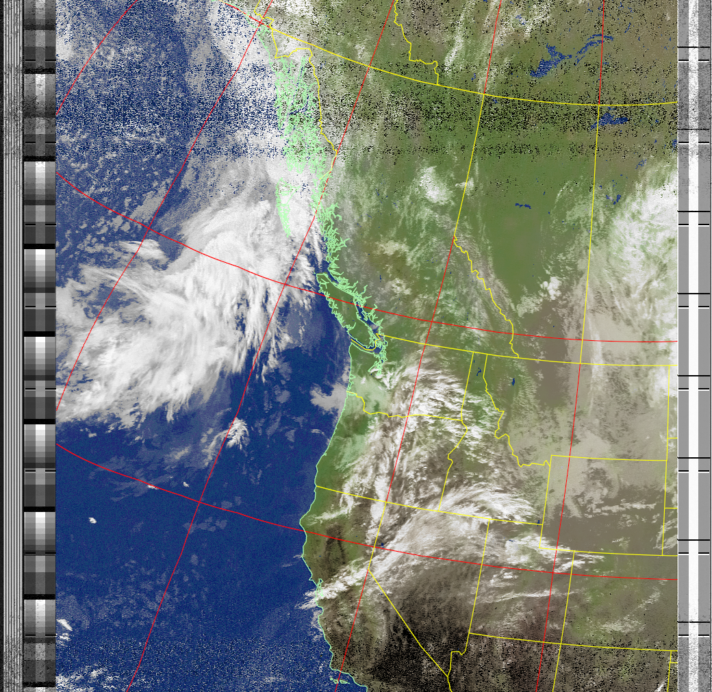
The first image is just contrast enhanced, and the map overlay was placed on, the second is a false color enhancement that helps show clouds.