
A few years ago, the idea came to me to build a binary addition machine as a display piece. The logic would be constructed of SPDT (Single Pole Double Throw) relays, which reduces the number of relays and simplifies the design a bit. The schematic represents a single Full Adder, eight of which will compose the full addition machine.

Note that A and B are the inputs from the two numbers, S is the output, CarryIN in the input from the previous bit, and CarryOUT is the output to the next bit.
My original efforts on this project were based on home etched PCBs, using the photo etching process I’ve posted about in the past on this blog. Here’s an example of one of the single sided boards I designed to compose a single Full Adder.

You’ll notice that some areas of the ground plane on the PCB seem to get a little spotty. It’s important to make sure you get the settings on your printer as dark as possible to avoid this. After tuning for my printer, I came up with the darkest print I could manage. The old transparency is on the top, and the new is on the bottom.

As you can see, it is a good bit darker on the new print, which leads to better etchings.
However, the whole process of exposing, etching, and cleanup is rather fiddly and time consuming, so I never managed to get around to making all eight Full Adders required to complete the machine.
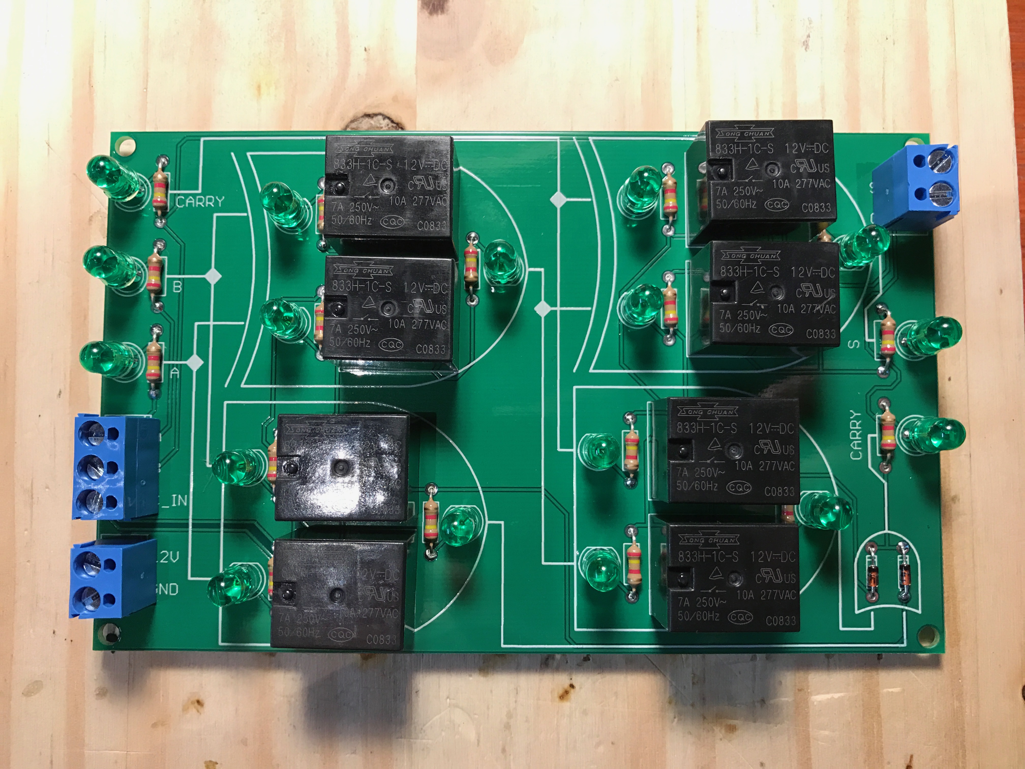
Several years went by with the project languishing in my random electronics box, and was recently brought back to light. I decided that I was going to design a new board and have it professionally made to save the time, and have a better looking end result, and work on making the mount and the various other bits as pretty as possible since the goal was a display piece.
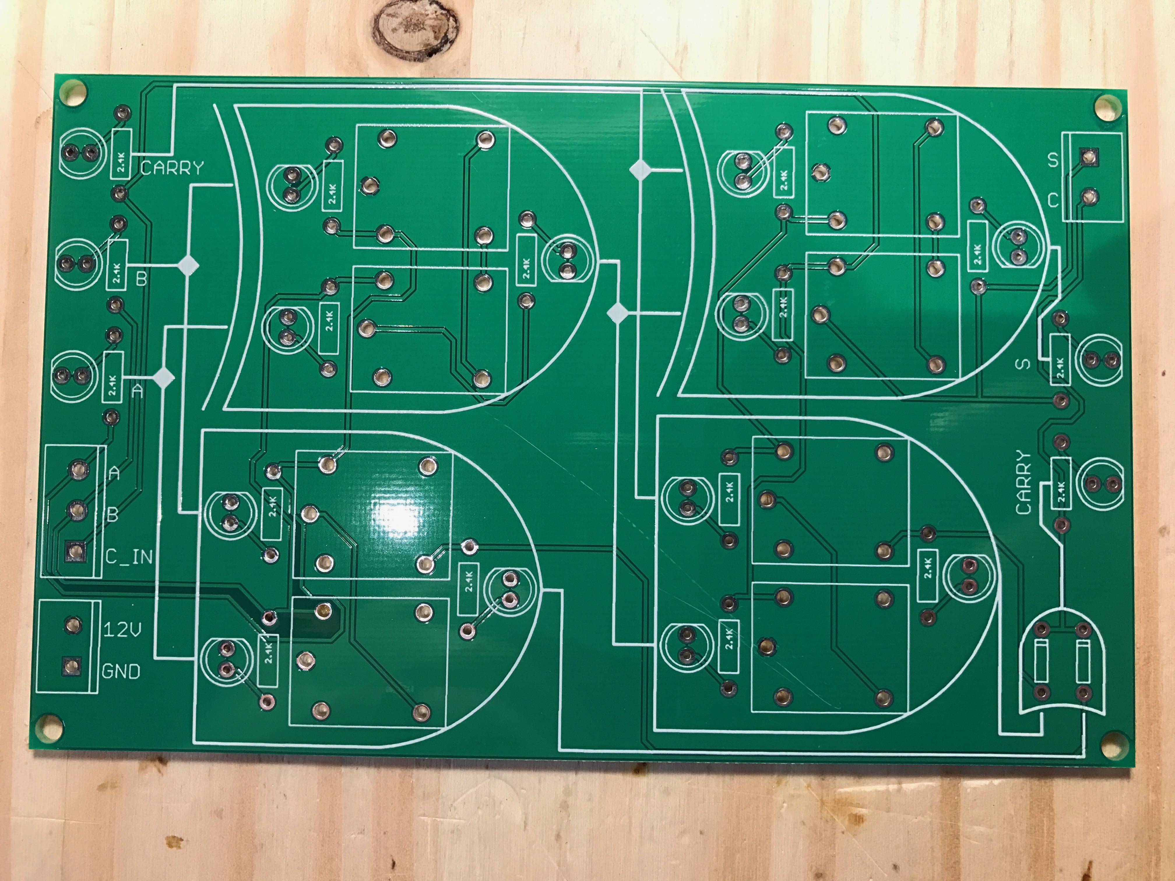
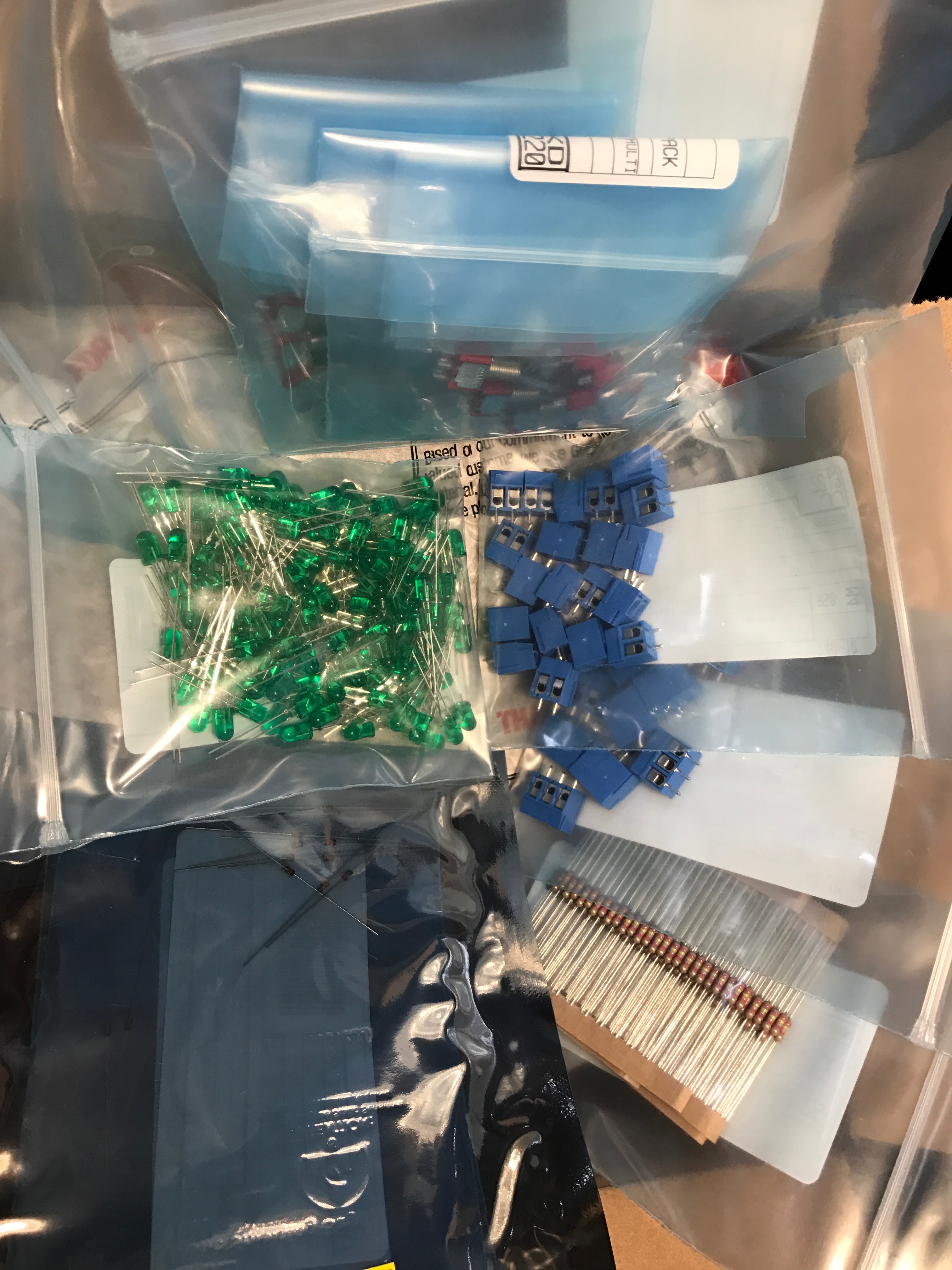
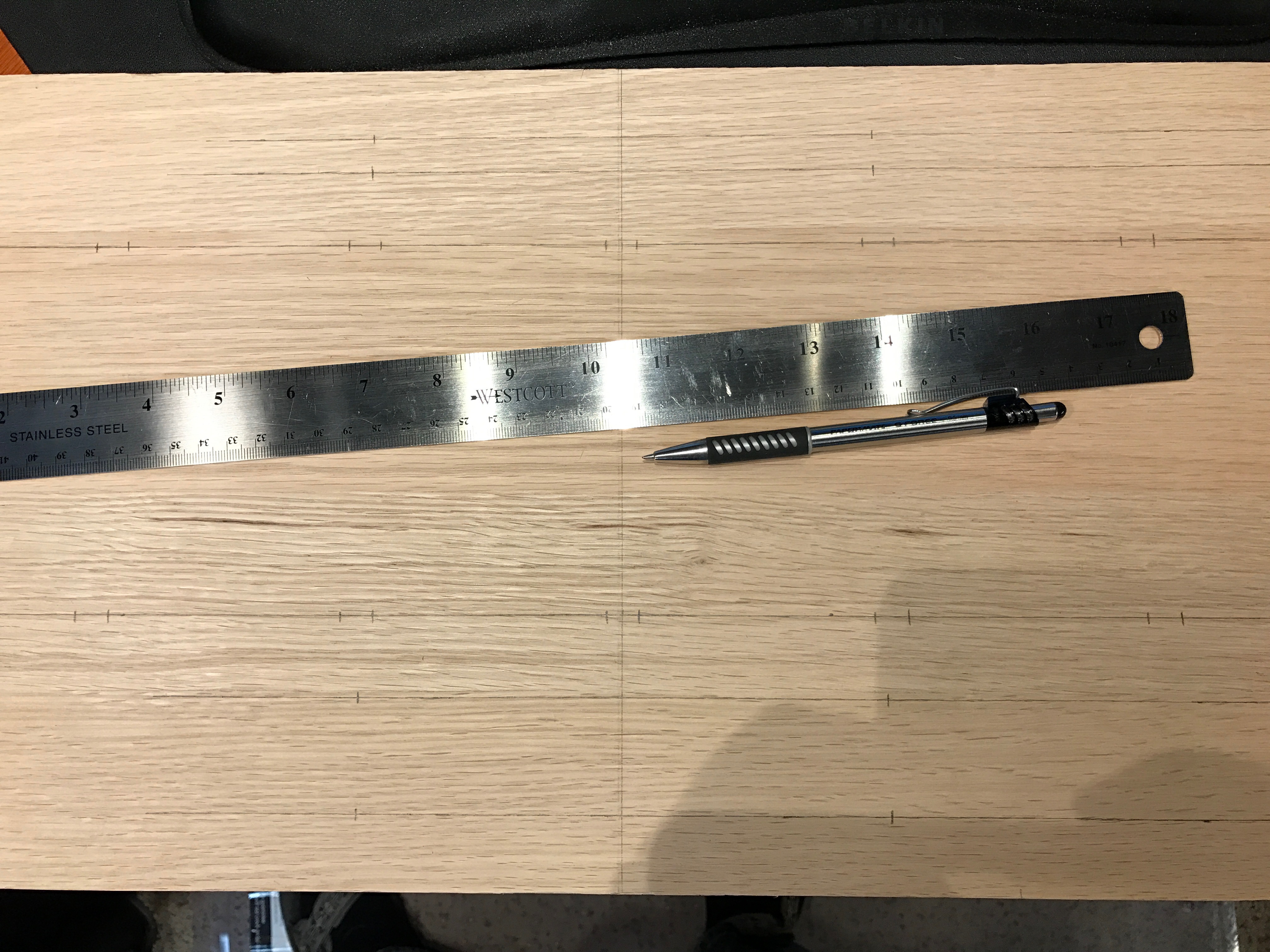
I ordered the PCBs and the parts to populate them, and in the meantime started work on laying out the mounting on a piece of Oak I picked up from the hardware store.
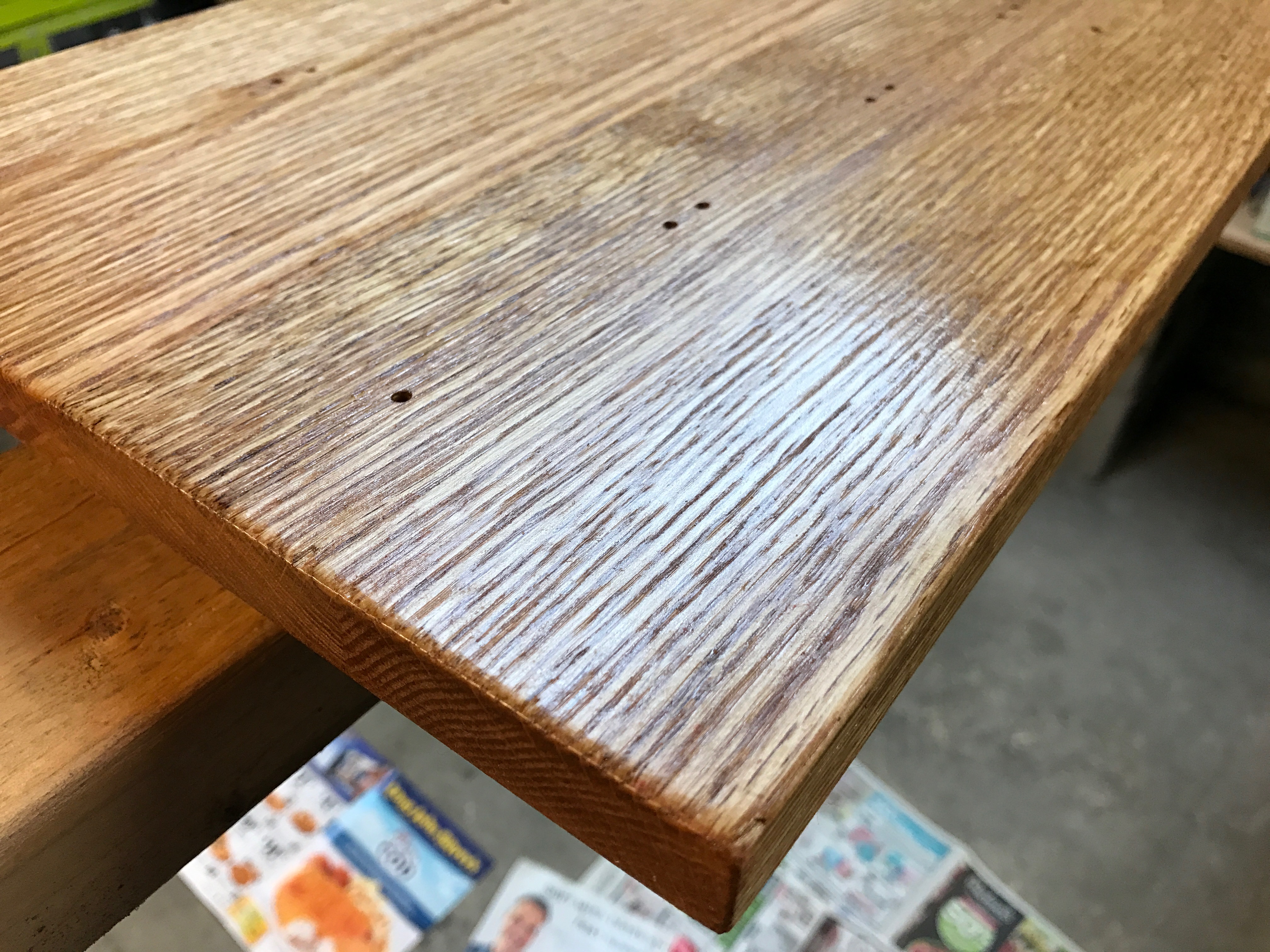
Once the mounting was all sorted out, there was lots of sanding and lacquering.
I decided I wanted to etch the labels into the brass plate that would hold the 16 bit switches (two eight bit numbers that get added together).
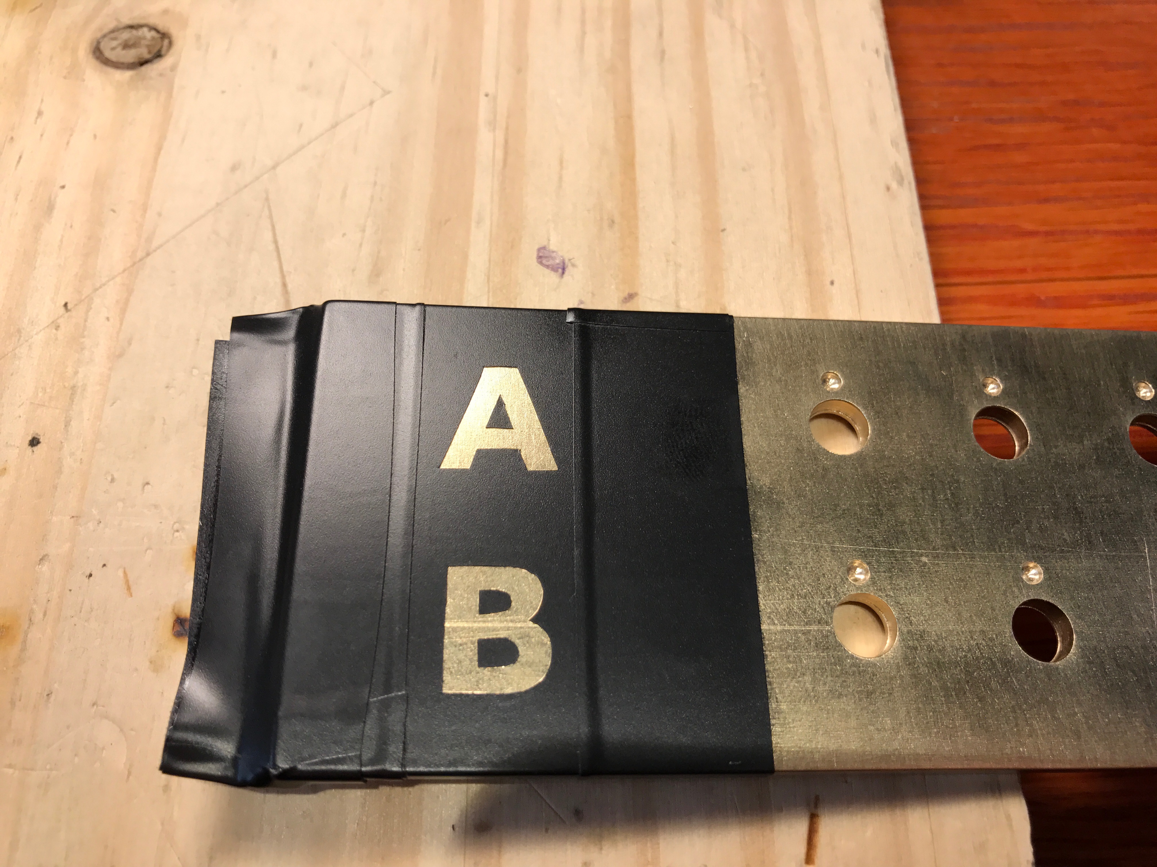
The etching turned out really well!

The display plate also got put together with nine LEDs (the 8 bit number and a 9th for the carry).

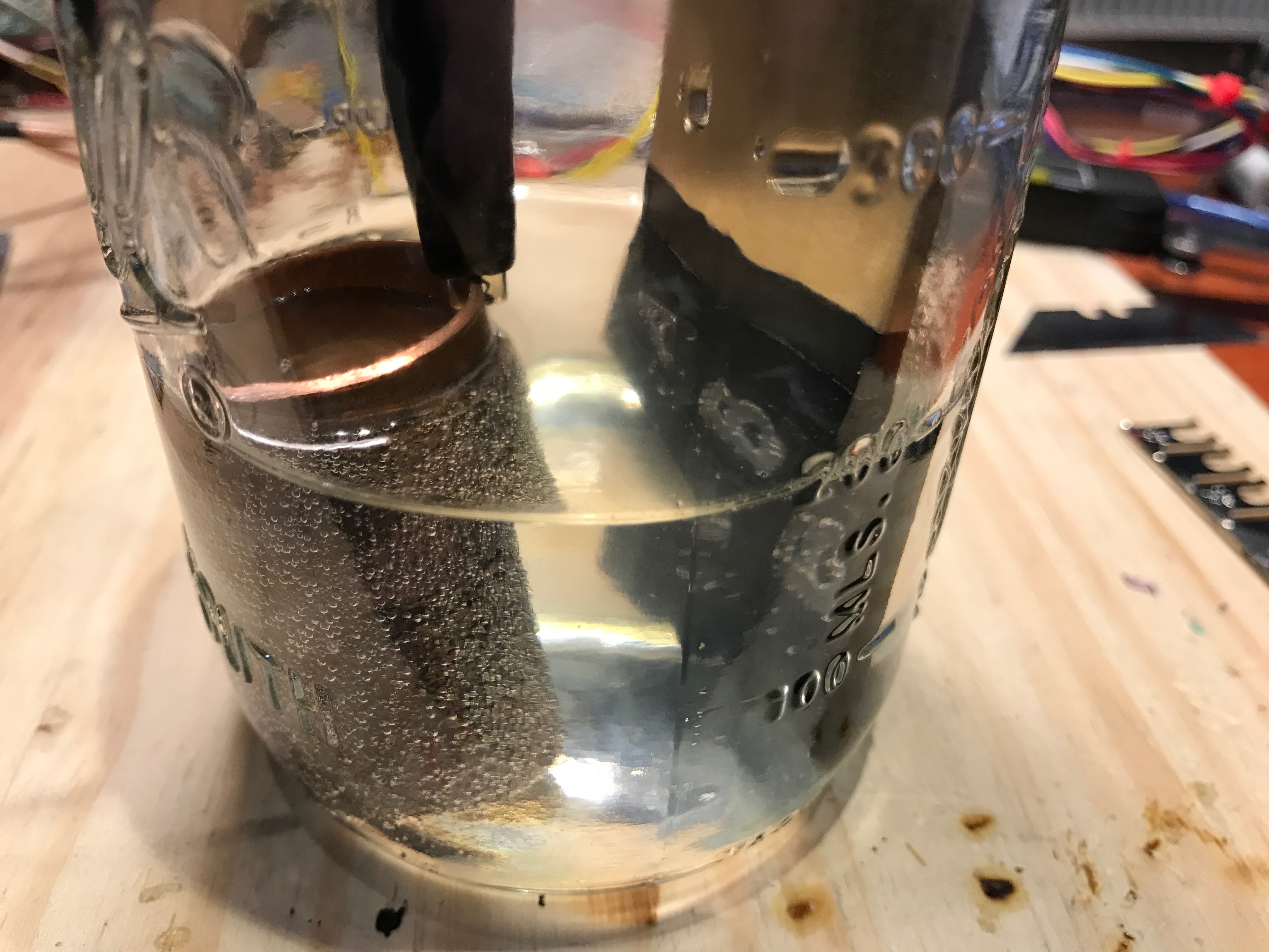
Instead of buying brass standoffs that would go with the switch and display plates, I bought a section of brass tubing, cut it down into equal lengths, trimmed the ends on my lathe, and brushed them with a wire wheel on my grinder.

Finally, it was time to assemble the boards.
And then get them mounted on the base.

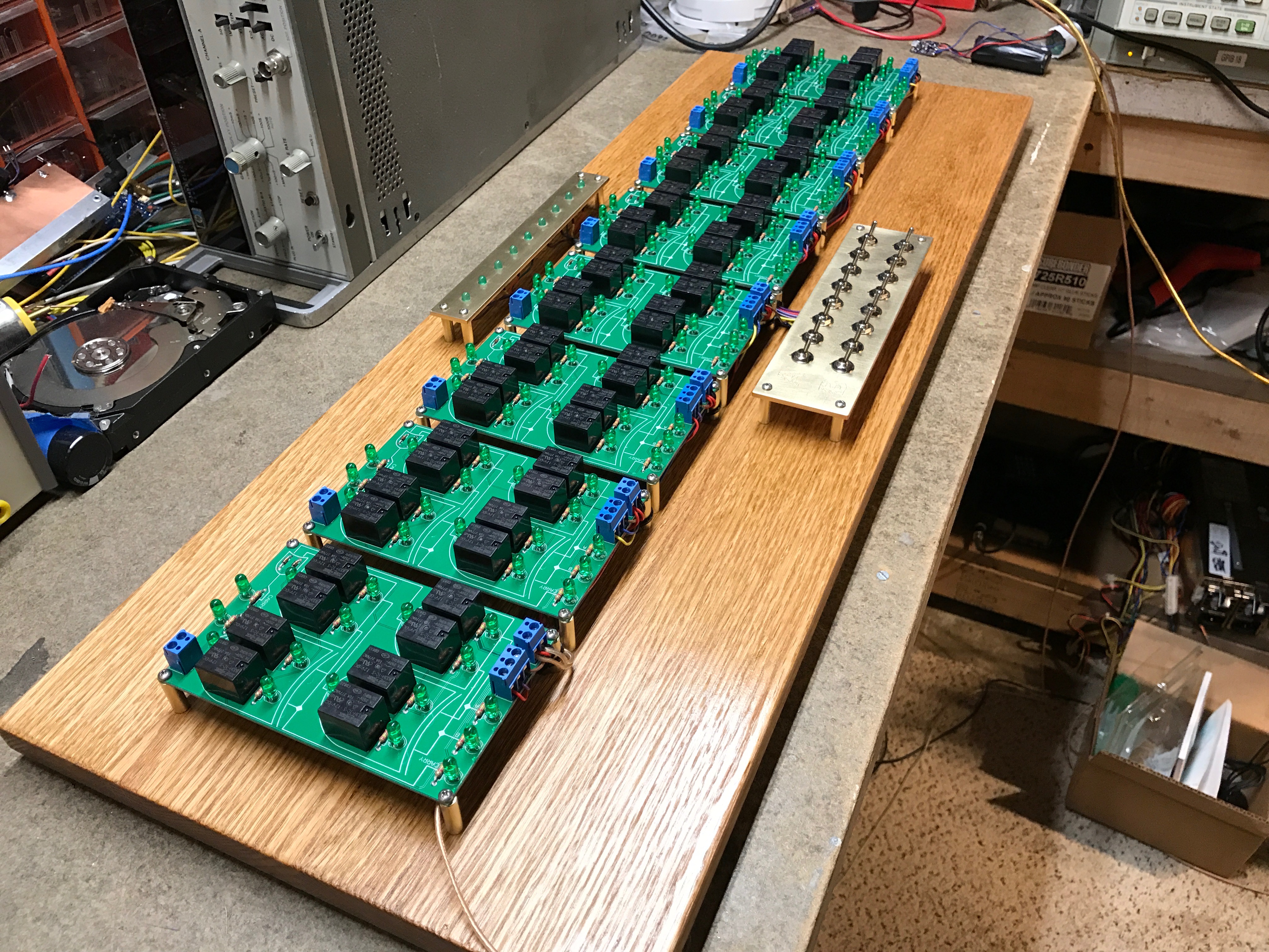
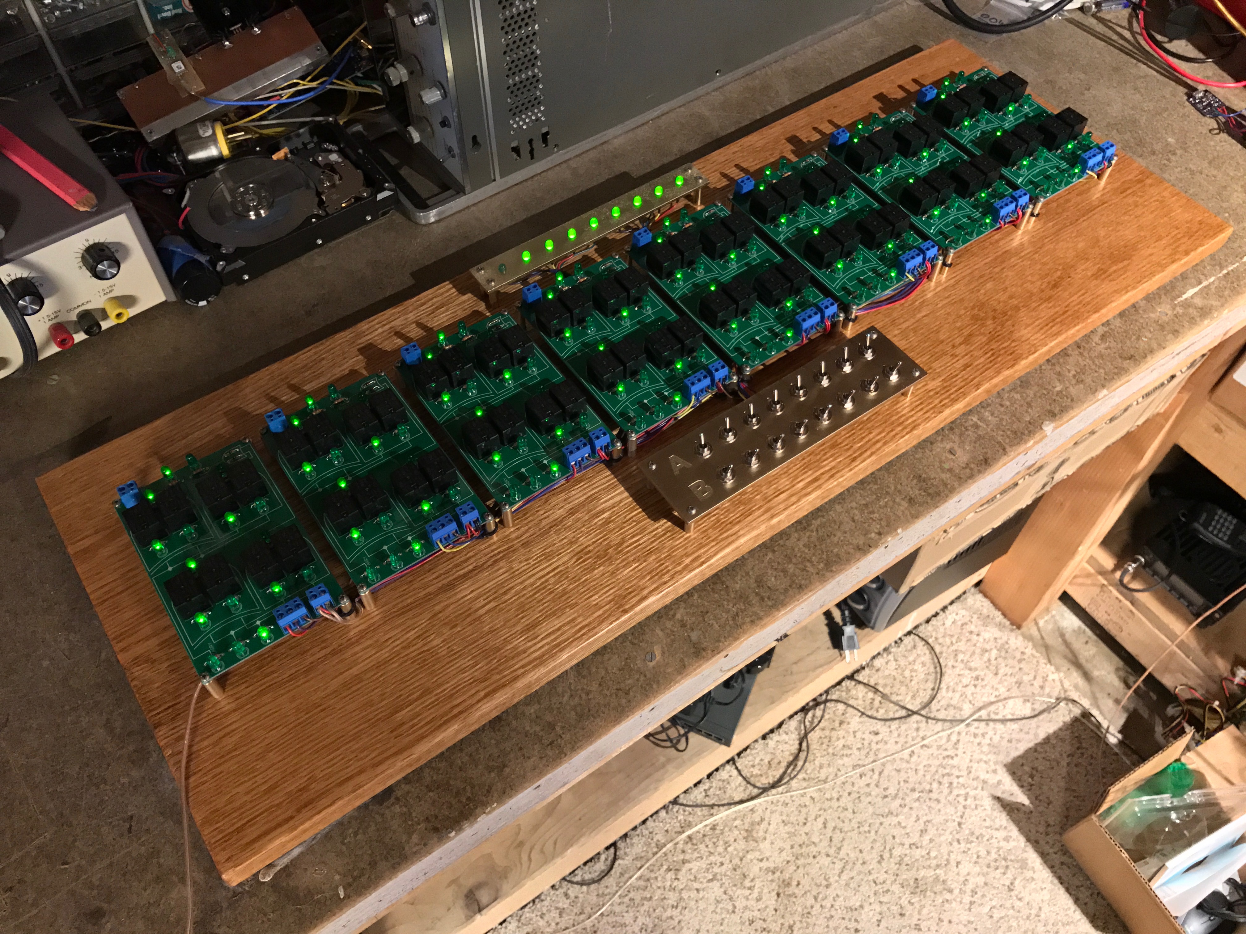
In the end, I’m extremely pleased with how this project came out, it’s a beautiful result, and is really fun to show people how the math works here. It’s also really neat to see the propagation delay in a multi-bit carry due to the relay switching times.