While it’s not particularly new or novel, I’ve long been interested in setting up an Oscilloscope Clock with one of the various kits that have been available for some time. Over the holidays one of the gifts from my family was based on this, and encouraged me to go further to build a clock around a raw CRT tube, rather than just something that interfaces with an existing oscilloscope.
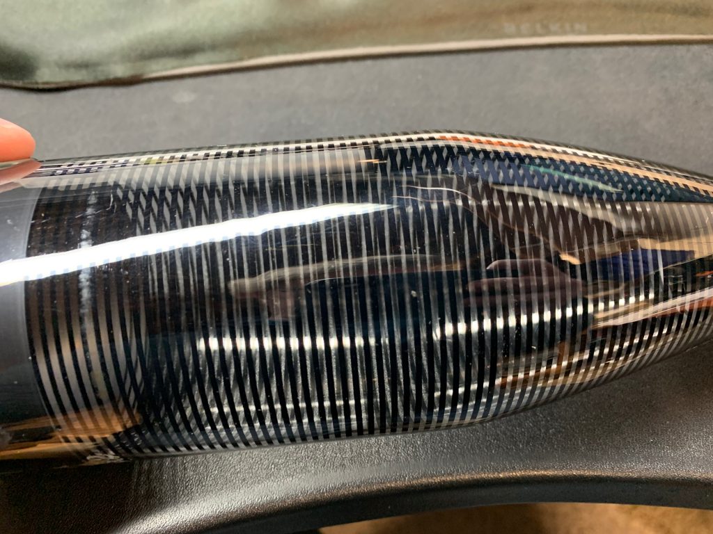
Soon enough I had found a real gem of a tube with a helical PDA, which I thought was just gorgeous.
The tube is a 3BFP1, which is a 3 inch, flat face, with a standard green phosphor like you’d see on an oscilloscope.
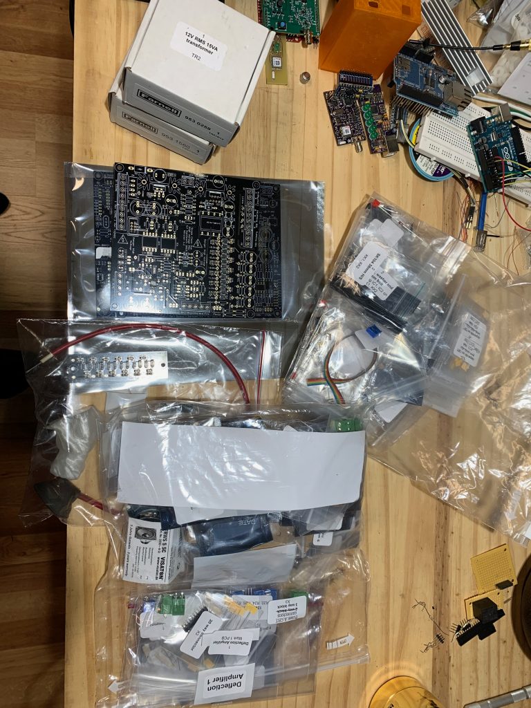
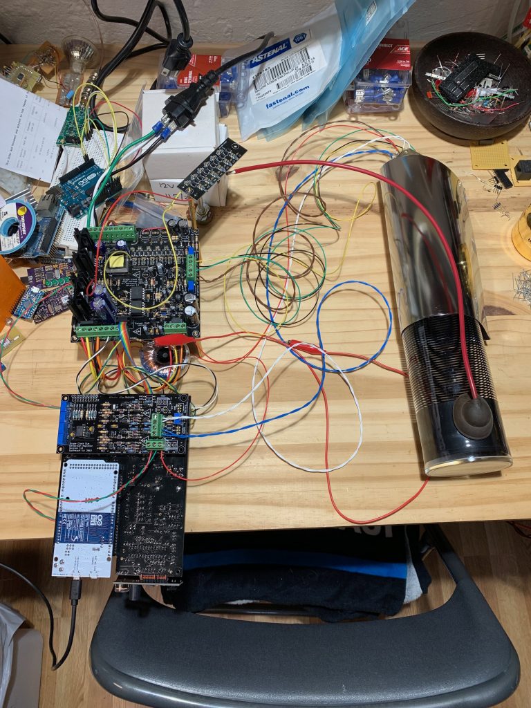
Next I needed a setup to drive the tube, which needs a number of various high voltage sources to drive it. I didn’t particularly feel like jumping into designing those circuits myself at the moment, so I found a kit from a fellow in the UK which handled the various power supply needs, and included a very smooth clock display board as well at http://www.sgitheach.org.uk/scope3.html
Soon enough the kit was in hand, and thus began a few evenings of soldering the kit together.
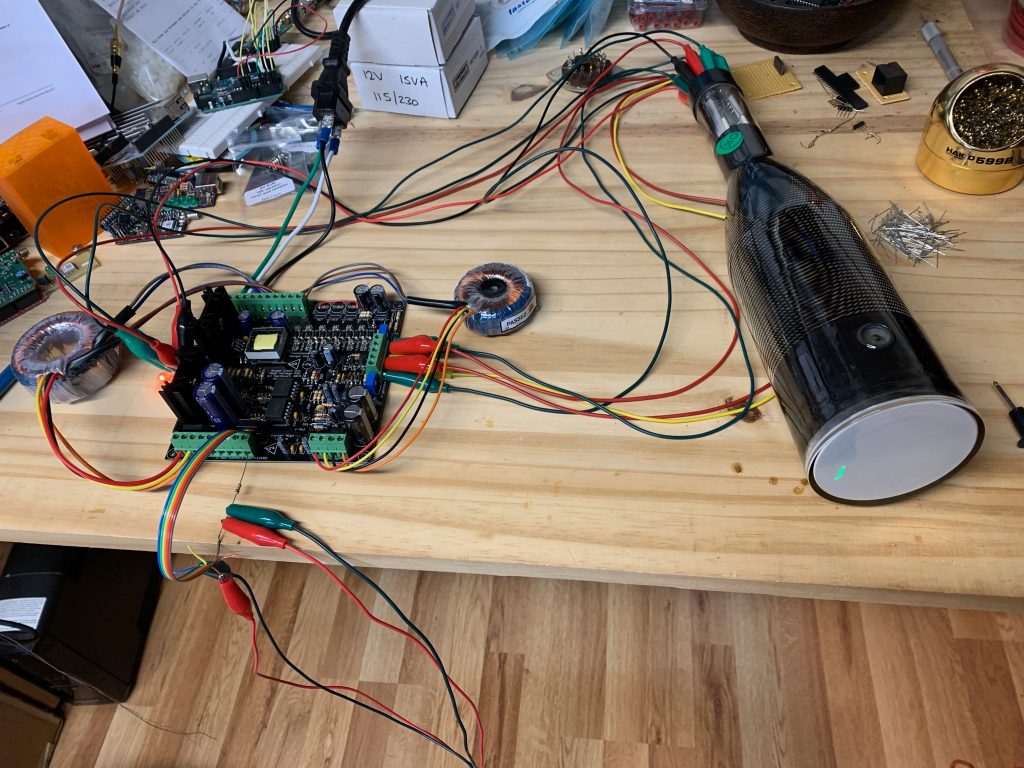
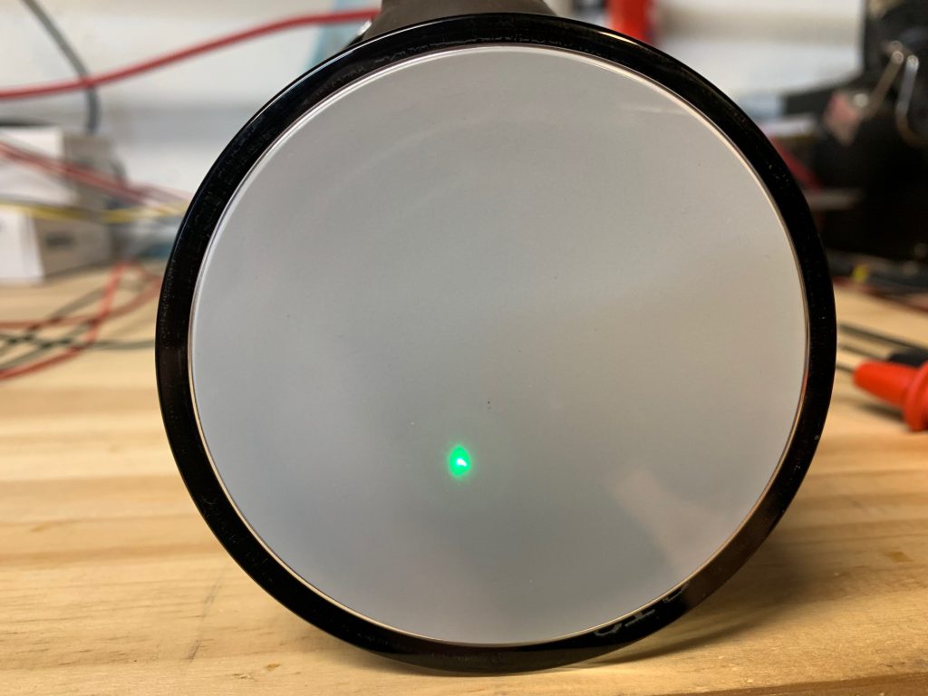
At this point I’ve got power to the tube, and first light. It’s still not well focused, but good progress. Next I move onto building the clock and signal amplifier boards, which will let me actually try displaying something on the tube.
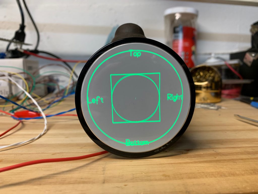
Finally some more work on getting the voltages tweaked to improve brightness and focus, and I had a display I was happy with.
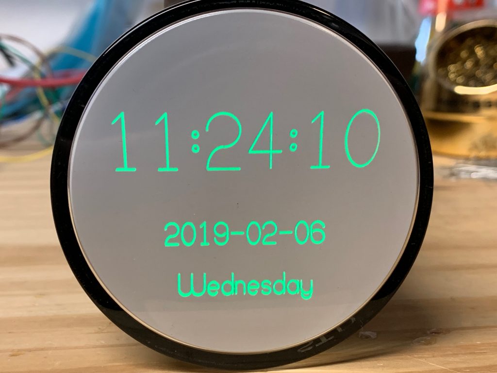
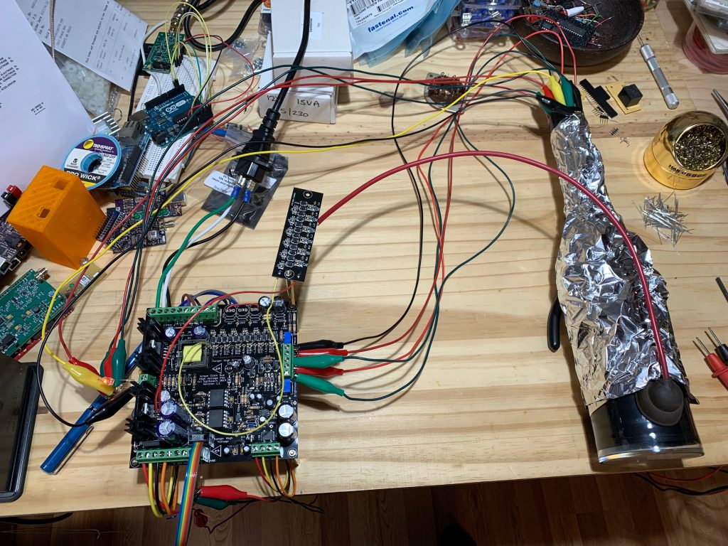
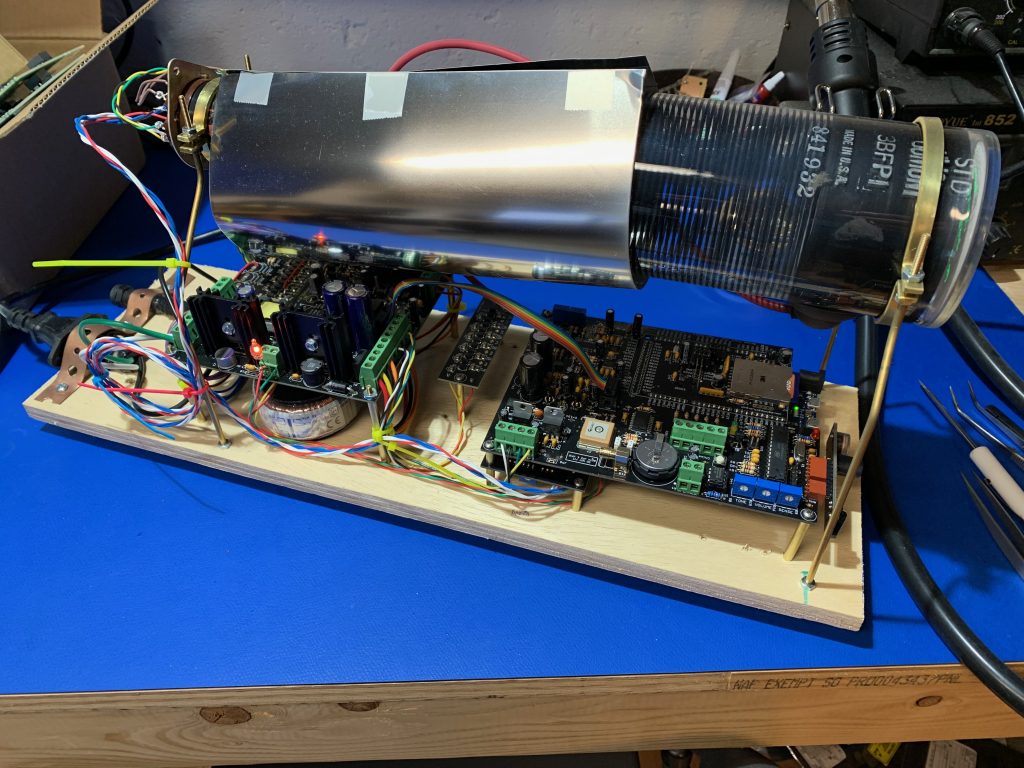
Not perfect, but there may also still be a little room for improvement when it all gets built into an enclosure when I add magnetic shielding. Next I started working on a prototype layout for all the components before I commit to things.
This is how it stands today. I think I’m happy with this layout, so now as I have the time, I’ll make a base out of some wood that’s a bit nicer than plywood, and work on an acrylic enclosure to keep fingers out of the high voltage bits, but still allow the tube to be on display.


