Windows 7 Display Issue

So, for quite a while now I’ve off and on been getting an error on my computer (Windows 7 64bit) that says that the “display driver stopped responding and has recovered.” Most of the time this would only happen once every few days, and it would just cause the screen to go black for a few seconds, and then come back with the error. Not really a productivity killer.

However, recently I upgraded my video card. (Was a NVIDIA GeForce 8800GTX, now is a NVIDIA GeForce GTX 260) Anyway, after upgrading the card. The same sort of thing would happen, however the screen would be freaking out for more like 30 seconds rather than 3, would show the same error message, then would bluescreen with an error involving “nvlddmkm.sys” Yes, BSODs are annoying, they crash your system. If it happens once a month, sure that’s an issue, if it happens as soon as you log in, you might as well not have a computer because this one sure doesn’t work.

Originally I thought that this might be an NVIDIA specific thing especially noticing the “nv” in “nvlddmkm.sys.” However, after doing a bunch of reading it seems that people are having a similar issue with ATI video cards, and an approriately titled .sys file. Points more towards a windows problem.

As is customary, all the nvidia articles pointed to microsoft. All the microsoft articles pointed to nvidia.

(May I note that the microsoft technet forums are mostly crap. The part that frustrates me the most is that the person asking for help generally isn’t the person who marks what the answer is. Generally some support drone answers with something that doesn’t actually fix it, then marks his/her answer as the right one. Not helpful.)

Anyway, I ran windows update, got all the newest crap. Downloaded the newest NVIDIA display drivers from NVIDIA. Neither of which fixed the issue. Finally got around to downloading the latest BIOS for my motherboard (ASUS M4A79 Deluxe) and so far results are promising. At least the system started up, let me check my email and browse the web for a few minutes without crashing, which is better than directly after the new card was installed. So hopefully this fixed it, and hopefully someone finds this helpful. I’ll edit the post in a day or so to reflect if the fix really is actually a fix.

Update #1
Nope. System crashed as soon as I started it up when I turned it on this evening. Trying something else now and will post later if it seems to be stable. So far so good.

Update #2
Nope. Nothing I’ve tried seems to work. I finally got pissed enough at not being able to reliably use my computer that I switched back to my old graphics card. For now the newer one will just have to wait. I’m not terribly disappointed, I got the card for cheap, and it was only a modest upgrade from what I’ve got. Oh well. On to normal life again.

Posted in Random, Technology | Leave a comment

GPS Tracker

Well, in my last post I talked about my new PCB Etching stuff. Well, I’m putting it to use relatively frequently these days, and last weekend I made a little widget to gather some data for me.

I thought to myself, as I was stuck in traffic one day. Since I’m commuting back and forth, to and from work each day on some of the local freeways around here, why don’t I make a GPS Tracker that I’ll stick in my car and will take position samples every so often. I can then plot these on a map, and associate speeds with the difference in time to the difference in position. If I do this for long enough, over the days / weeks / months / etc. I can get data on traffic over my commute route and correlate that to other phenomena going on, like weather, events, or etc.

So I did.

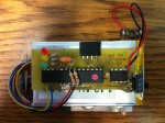
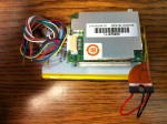
It’s an ATmega 328P (The same that’s what’s on the basic Arduino). With a 256Kb flash chip to store the data. Couple that with an old iPhone 3GS battery (A friend of mine asked me to replace the one in their phone with a new one. I kept the old one) and a Garmin 15L GPS module. Stuff a little bit of code on the microprocessor, and you’ve got yourself a GPS Tracker.

Hopefully soon I’ll have a page up where you can view some sample maps or something. For now you’ll just have to enjoy the pretty pictures of the device itself.

Posted in Life, Technology, Vehicles | Leave a comment

PCB Etching

Got a package in the mail today. You know what was in it? Nope. But I’ll tell you! Stuff to make better PCBs!

My previous attempts at etching my own circuit boards ended up a little crude to say the least. Using the toner transfer method, perhaps the simplest and cheapest method, my circuit’s traces would melt together, or wouldn’t transfer entirely, so I’d have shorted or broken circuits. Bad stuff. To summarize, it wasn’t pretty, it wasn’t accurate, it really wasn’t workable. When you have to attempt it three or four times to get one that actually is workable, it’s not worth the effort anymore.

Needless to say, I got tired of it sucking. Yes, yes, I know. Some people have very good results with the toner transfer method, some people never have traces melt together, or incomplete transfers. I cannot say that I have EVER had any of my boards come out right. Most of the time, I do it several times over, and it comes out marginally passable. So, I moved up to the next step. I’m now doing etching with photo resist.

Now I print my design on a transparency, place it over a PCB with a photosensitive chemical on it, and expose it to UV light for a few minutes. After that, I take the exposed board, and place it in developer. The developer removes the chemical in the areas exposed to UV. Leaving the stuff behind protected by the transparency to protect the copper underneath.

Next you take the board with the excess photo resist removed and place it in Ferric Chloride. This removes all of the unprotected copper.

Once that’s done, simply wash off the photo resist with some rubbing alcohol, and all of a sudden you’ve got a printed circuit board with traces about as accurate as you can print.

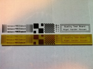
Here’s a photo of a test board I did this evening.

You’ll note that the stuff near the top may have been eaten away a little. There’s kinda two things going on there. One is that I should have exposed the board for a little longer to the UV light. Second is that the top edge of the board after cutting was a little rough, and pushed up on the transparency, since the transparency was lifted up, UV light could get underneath near the top edge, so some of the lines got partially washed away.

You can see however, that there is significant accuracy available. From left to right, there are traces decreasing in thickness down to 0.008 inches, then there’s various sizes and thicknesses of text, then there’s several 0.010 inch traces placed increasingly closely together. Then there’s two checker patterns, to see 1, how well the corners connect, and two how larger areas of protected copper hold up, then there’s holes of various sizes, then is a label with a few long traces run around it to see how well long traces hold up.

Overall I’m very pleased with the results and plan on doing some more testing and creation of actual circuit boards here in the near future to progress some of my projects that have kinda been on hold.

Maybe I’ll even etch some business cards. (Really expensive business cards.)

Posted in Technology | Leave a comment

Homebrew Battery Analyzer

Recently I borrowed a battery analyzer from a friend of mine to test a bunch of lithium batteries I had laying around. I found it to be a very useful tool and thought about the concept of making one rather than buying one from West Mountain Radio

So, I dug around through my pile of scrap bits to see what I could scrounge up to put this thing together. Found an old processor heatsink/fan to keep things cool, found a big mosfet from an old laser printer to control the current flow, grabbed an old 50W halogen light bulb to use as the power resistor E.G. the load, and a 0.11 ohm resistor to measure the current flow with. With these few bits, I had the majority of the system.

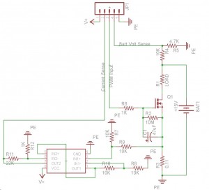
Now I had to design a circuit setup that would combine these bits into a working instrument, as such I came up with this:

You’ll note the only bit on the schematic that isn’t really representative of what it really is, would be the box near the bottom, that’s a dual op-amp. More specifically the MCP6L92. It’s a basic differential op amp with the addition that it’s a Rail-to-Rail amp meaning that the output can get very close to either ground or the positive rail. That’s an important factor in this circuit, as the current measurement circuit puts the output very near to ground.

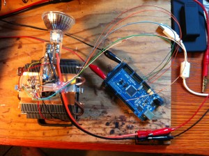
Anyway, I used the toner transfer technique and etched a couple of small circuit boards, put the bits on them, and wired them up. Here’s the result of the circuit along with the inputs/outputs connected to an Arduino.

So, to summarize, the arduino runs the show, it measures the battery voltage (to know when to stop discharging), measures the current flow (to integrate the Ah capacity of the battery and to regulate the current at a value I want), and outputs a voltage signal to control the mosfet to regulate the current. We start by ramping up the voltage output till the current measured hits the set point, generally 1 Amp. Then we continue to measure the current, adjust the set voltage, and integrate the time and the current draw to get our capacity, and then shut the system down when the battery voltage gets down to the minimum voltage (Most batteries don’t like actually being discharged to ‘0’. A 0% charge is actually generally significantly above 0 volts).

Anyway, it seems to work great. I’m quite pleased with it, and based on having a stash of parts, my new battery analyzer cost me a total of $0 (Sure, some of those parts I may have bought for cheap a few years ago, but I mean that I didn’t have to go buy anything for the project).

Posted in Technology | Leave a comment

2011 Balloons Launch

Our 2011 launch was completed Saturday, May 21st, and summary data is listed below.

Payload A launched at 22:51 UTC, reached a maximum altitude of 19786 meters, total flight time was 90 minutes, and time after landing till the payload was retrieved was 30 minutes. The lowest temperature recorded was -51 degrees Celsius. The lowest barometric pressure recorded was 53 mBar.

Payload B launched at 18:54 UTC, reached a maximum altitude of 34730 meters, total flight time is unavailable and time after landing till the payload was recovered is unavailable as the payload was not recovered. The lowest temperature recorded was -53 degrees Celsius. The lowest barometric pressure recorded was 17 Torr. Please be aware that there is somewhat more uncertainty in the dataset for Payload B as the radio data link was lost shortly into decent and the payload was not recovered, so data stored onboard is unavailable.

Posted in Electronics, Projects, Random | Leave a comment