DC PDU Project

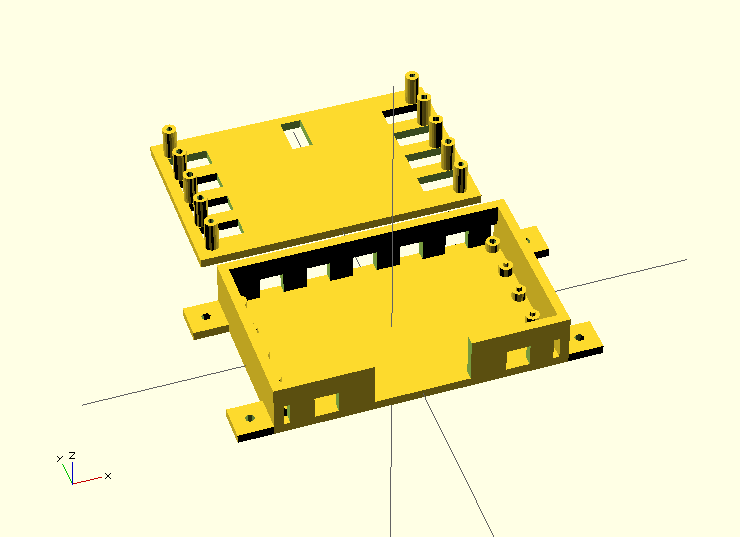
I mentioned a post or two ago that I was working on a project, and had designed a 3D printable case for it, and that I’d get back to posting about the project itself. So, I’d like to introduce my DC PDU (Power Distribution Unit)!

IMG_1975

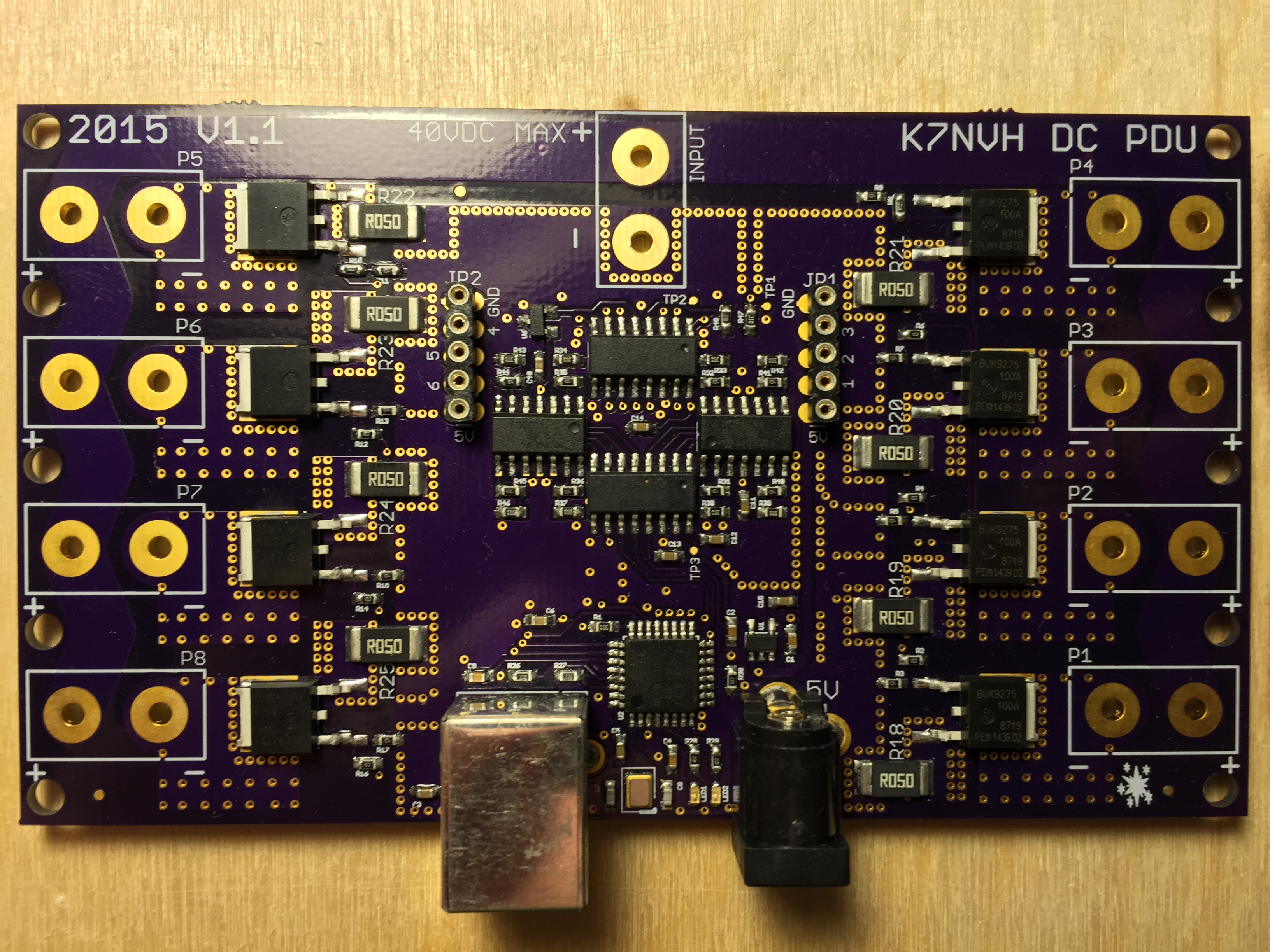
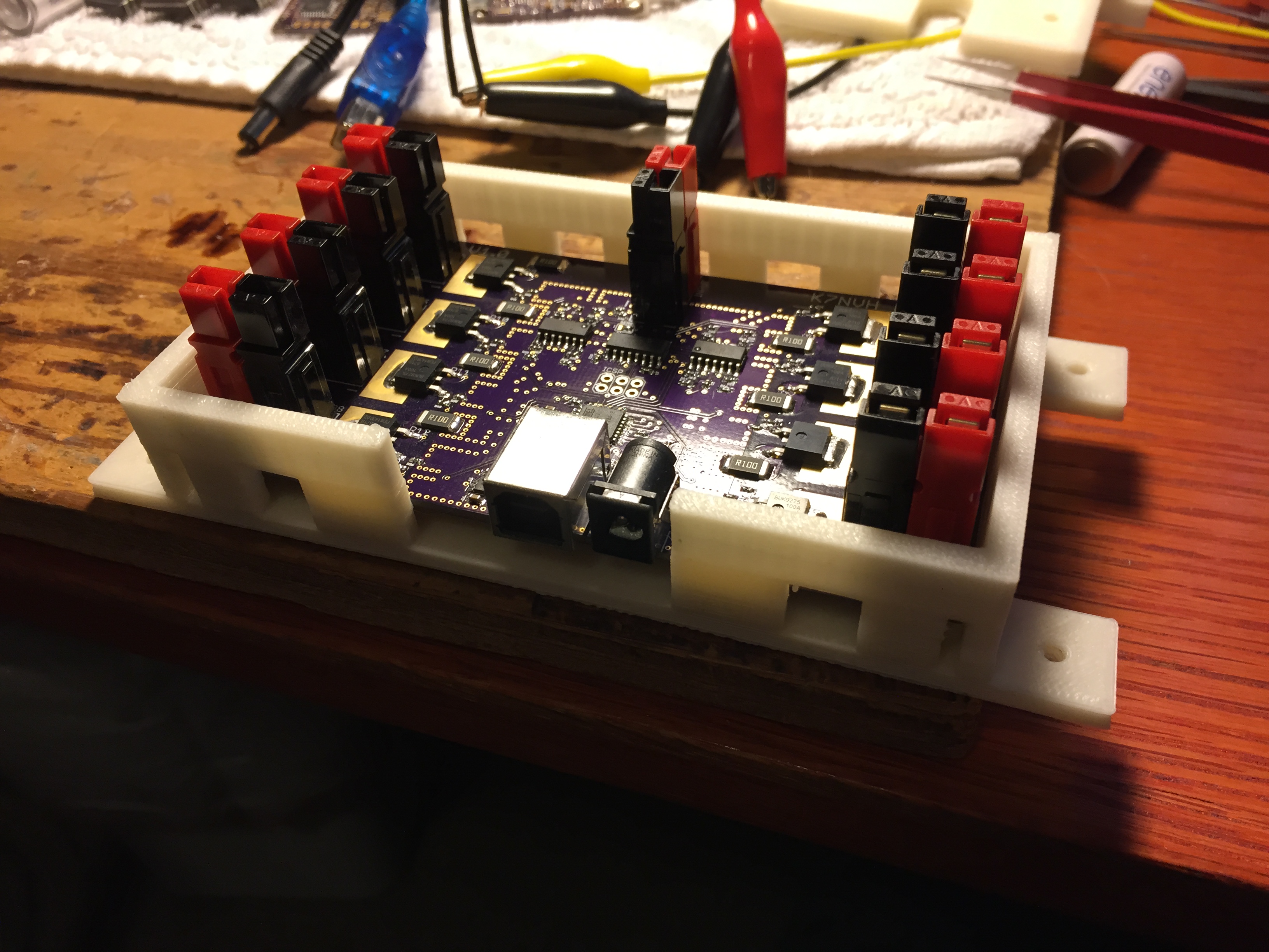
The design goals here were to create essentially a remote controllable power strip, for DC powered devices. You have one input port that gets distributed to 8 output ports. Each output is individually controllable, as well as individually senses the power flowing through the port.

PDUs aren’t new devices by any means. There are a large variety of PDUs made by companies like TrippLite or APC. However, these are almost universally AC power devices. These devices are designed to sit in a datacenter or with other information technology, and allow administrators to control power to servers and networking gear remotely.

Let’s imagine that you have a remote location where you have some solar panels, batteries, and your devices run on DC power. If you want to be able to control power to these devices with a PDU, suddenly you need to add an inverter, as well as converters back down to DC power on either side of that PDU. It introduces a lot of cost, and more importantly, a lot of inefficiency. Each of those conversion steps throws away power, and with limited power budgets like you see with many solar setups, these are losses that you really can’t tolerate.

I’ve run into this exact situation with a project I’m working on in the local area with some other folks, so I decided to build a PDU that would work directly on DC power. No conversions needed. The PDU itself would draw very little power managing the logic, and there wouldn’t be any conversion losses.

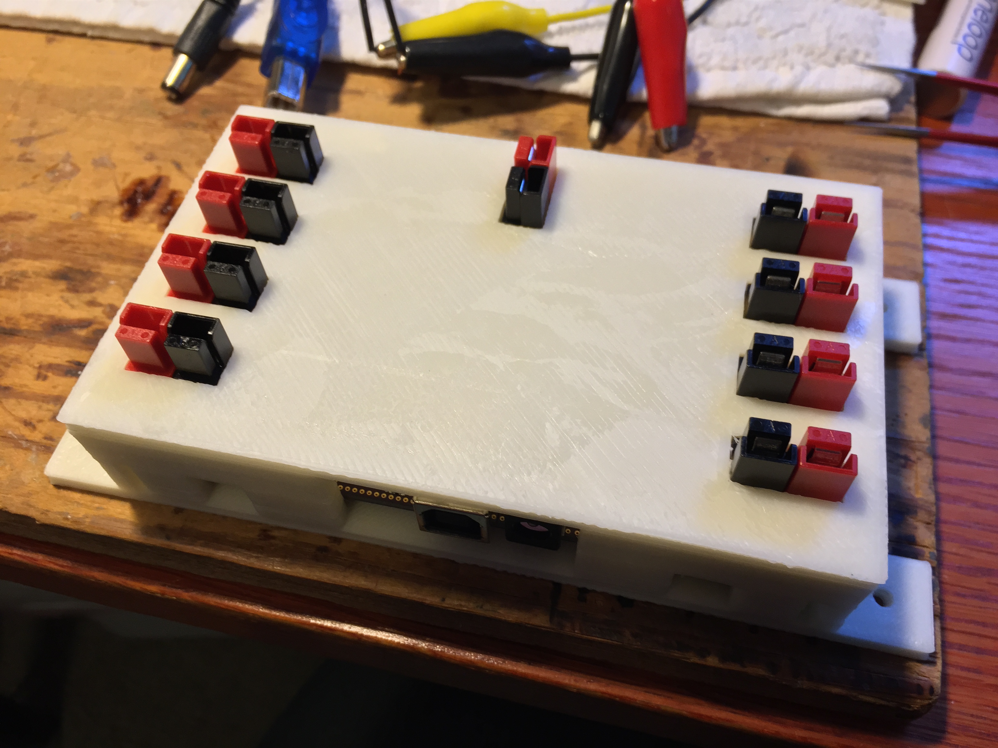
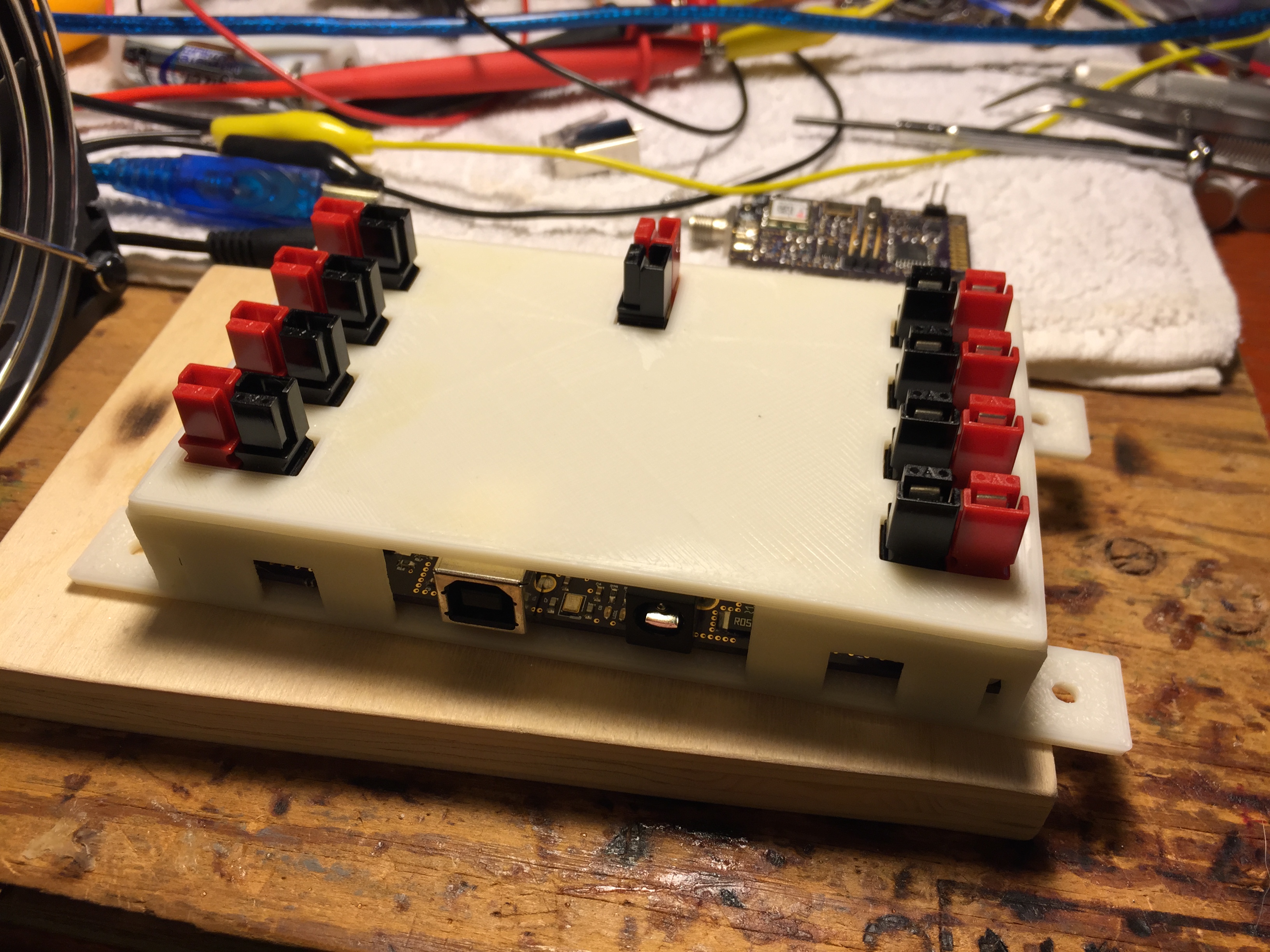
Combine it with some connectors, and a case, and you have a complete device for managing power at remote locations!

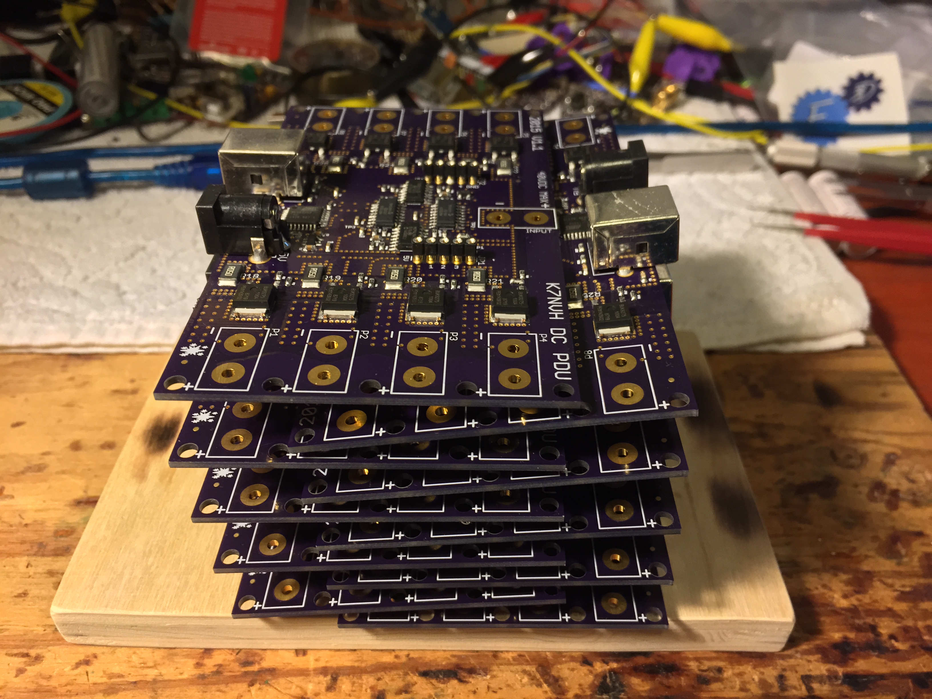
I’ve built a small stack of them so far…

IMG_1871

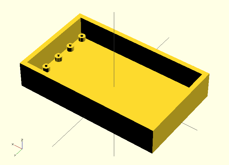
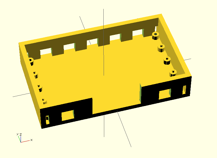
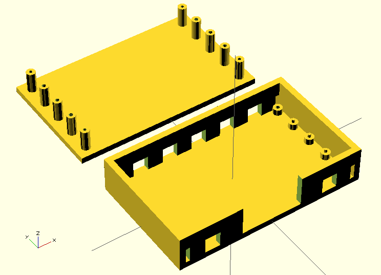
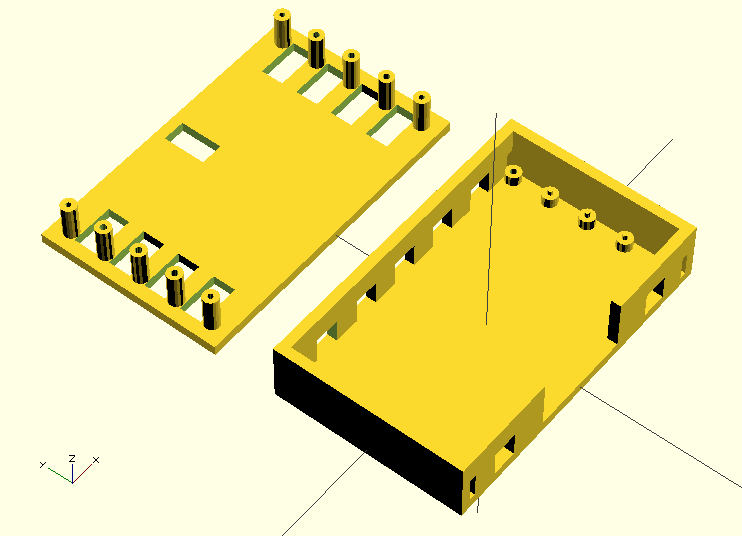
And printed some cases as well.

IMG_1966

While I built the device to serve my needs, and the local project, I figured it may have broader appeal, so I’ve also decided to try my hand at selling them. I’ve created a store on Tindie, and added my product. https://www.tindie.com/products/nigelvh/dc-power-distribution-unit/

I’ve also made the firmware the runs on the device available on GitHub, so that folks who are interested can modify or contribute to the project, or at the least, if they notice any bugs, they can notify me there so I can fix them and release a software update. https://github.com/nigelvh/K7NVH-DC-PDU

I’ve had reasonable luck so far with selling a unit or two, and I’m hoping that over time I’ll see more sales and word of mouth will spread. If it doesn’t, I built it for my needs anyway, so nothing lost there, and if it does, it’s a nice little bonus.

Posted in 3D Printing, Electronics, Ham Radio, Projects, Technology | Leave a comment

Pacific Northwest Rust

Those of you who live in the Pacific Northwest, particularly along the coast, know that just about anything metal you leave outside will be rusted in very short order. The mild temperatures and moist climate tend to encourage such things.

If the paint on something gets chipped or scratched, you can about guarantee it’s going to be rusting before long. Well, where might you expect to find chipped or scratched paint? On a motorcycle!

We had some decent clear weather recently, so I decided to take the opportunity to try and clean up some of the rust on my motorcycle. Some of it was there due to dropping the bike, or rocks causing chips in the paint, but there was quick a large amount of rust on the rear rack, that seemed to just come with a poor paint job from the aftermarket manufacturer!

IMG_1837

So, I went to work with a wire brush on the dremel tool to try and grind away some of the rust in various little spots on the frame of the bike, and took more expansive rust, like on the rack, to a friend’s house, who happens to have a grit blasting chamber.

After blasting and cleaning and a few coats of spray paint, the rack was looking pretty shiny!

IMG_1857

Now, I didn’t have time to disassemble the whole bike, clean every last bit of rust on the thing, repaint, and re-assemble, but I did cover a lot of ground, and every bit helps in maintaining it!

IMG_1853

Posted in Life, Projects, Random, Vehicles, Weather | Leave a comment

New 3D Printer Hotend

I’ve had my 3D printer for a while now, and have been fortunate in that most of the parts used in it were given to me by a friend who had spares or samples companies had sent. While it worked, and worked well in a lot of circumstances, I was fighting to try and get the quality I wanted out of prints, as well as fighting the hotend to reach and maintain a temperature for some of the higher temperature materials like ABS.

I decided that I would replace the existing hotend with a new one from E3D. Specifically, the E3D-V6.

They’re pretty highly reviewed, and relatively inexpensive, so I ordered one up, and waited for it to ship over from the UK. Once it arrived, I got to have a nice little unboxing, and got to work on getting it installed.

IMG_1794

It took a couple evenings of work to get everything set up properly and whatnot, but pretty soon I had a new working hotend.

IMG_1796

And here’s a neat little time lapse video using the new hotend to print the top of the case I designed in my last post.

Posted in 3D Printing, Electronics, Technology | Leave a comment

3D Printed Case

I’ve previously posted about building and printing objects with my 3D printer, but I thought I would show a bit more of some of the steps involved in making an object. In this case, I have a circuit board (which I’ll discuss in another post), that I wanted to make a case for.

For the most part, for me this means that I’m going to design a case. If it were a common sort of device like a Raspberry Pi, there’s a million 3D printable case designs on thingiverse. Since this is a custom board, I’m going to need to make one. I can’t say I have a whole lot of experience with 3D CAD programs, nor am I willing to spend the dough on a professional one like solid works, so I use OpenSCAD, which uses a programming language type environment to define 3D objects.

I didn’t grab screenshots right at the start, but this is still fairly early on. I’ve defined the general shape of the box, as well as some standoff supports for the board.

Screen Shot 2015-02-15 at 11.40.49

This board will put off a bit of heat though, so I need to add some air vents. I’ll remove chunks from the longer walls of the box.

Screen Shot 2015-02-15 at 12.17.37

Of course, the box will need a lid, and we’ll make posts that reach down to mate with the supports on the bottom, to hold the board in place. We’ll also screw the lid down through the bottom to hold it in place.

Screen Shot 2015-02-15 at 14.01.05

Next, we need to add the holes in the lid for the connectors to fit through. Otherwise we can’t actually attach anything to the board.

Screen Shot 2015-02-15 at 14.44.32

Finally, lets add some mounting tabs to the case so we can attach the case and board to a board or something to keep it positioned where we want it rather than hanging in the breeze.

Screen Shot 2015-02-15 at 15.52.22

Finally, let’s print the thing!

The board in the bottom portion of the case with no lid.

IMG_1767

A view of the lid upside down before attaching it to the box.

IMG_1769

And finally, the box assembled with the board inside.

IMG_1773

Posted in 3D Printing, Electronics, Projects, Technology | Leave a comment

Saleae Logic Analyzer

Recently I found that Saleae released new revisions of it’s Logic line of logic analyzers, and decided it was finally time for me to pick one up. I hadn’t played with one before, though I had seen shots of their software in use, and was impressed with how easy it looked to be able to capture and decode various protocols.

Previous to now, I’ve muddled through with my oscilloscope that doesn’t have any storage functions, or using an Arduino to try and capture data and manually parse it out afterward. Needless to say neither of these methods is terribly friendly.

As I don’t usually need a ton of channels, I got the Logic 4. It came in a handy little soft case that has all the bits you’ll need to get going.

IMG_1587 IMG_1589

And then of course the device itself.

IMG_1593

Of course, then you need to hook it up to something and try doing a capture! I tested it out with a USB->TTL converter I had laying on my desk, and sent a quick serial string, and let the Logic capture and decode it!

Screen Shot 2014-12-12 at 2.24.33 PM

Pretty shiny! I’ve already been using it to do some work on decoding some amateur radio transmissions that don’t seem to be well documented. Even though there isn’t an decoding function for this protocol yet, being able to capture the whole waveform makes a significant difference in being able to understand what’s happening in a given transmission.

Screen Shot 2014-12-19 at 8.28.41 AM

I’d also like to take a moment to commend their staff. I ended up having a problem with a minor physical defect on the device, and their staff was extremely helpful and friendly in resolving my issues. Really appreciated them being so straight with me.

In summary, if you’re in the market for a logic analyzer, I have to say I’ve been pleased with the Logic so far!

Posted in Electronics, Projects, Technology | Leave a comment