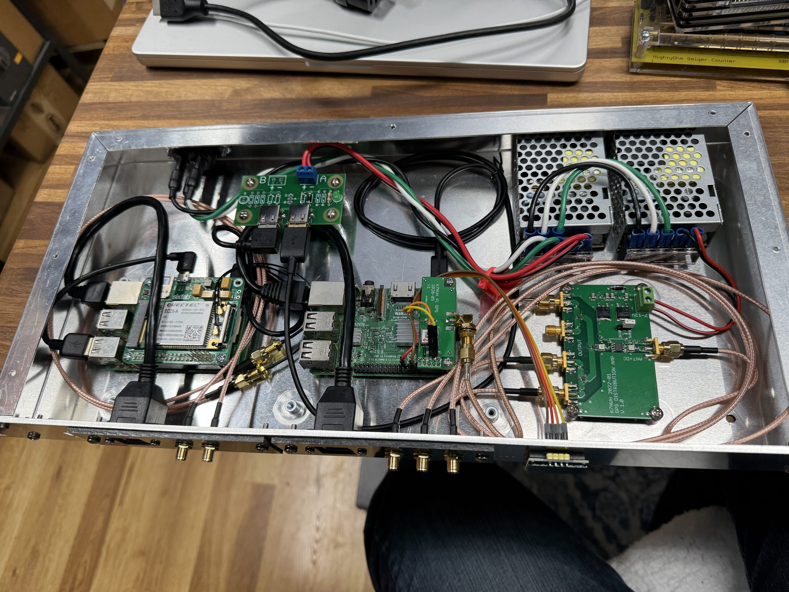
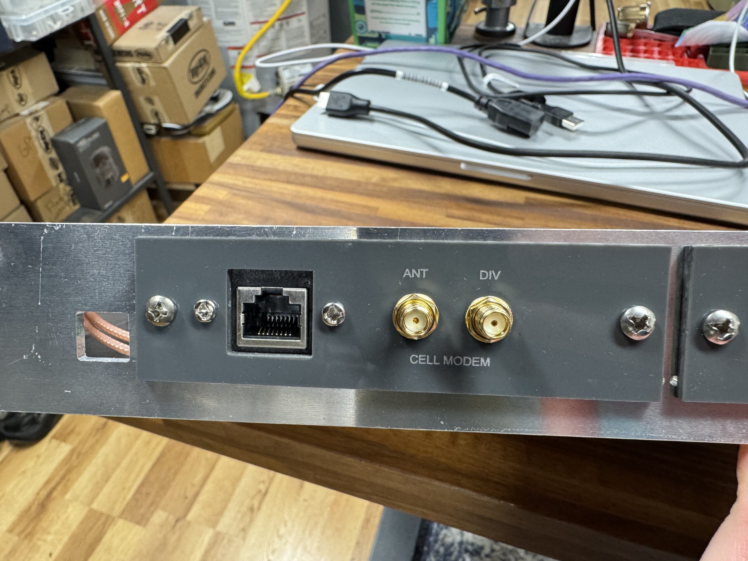
A few years ago I posted about a homebrew box I made containing a cell modem, a GPS receiver, and a couple of Raspberry Pi SBCs to handle Out-of-Band access to my gear at the datacenter where I only have one transit connection, and provide Stratum 1 NTP for my gear.
I’ve recently been working on cleaning up/modernizing some of my infrastructure here at home as well, and decided to build another unit, tweaked to the needs here at the house.
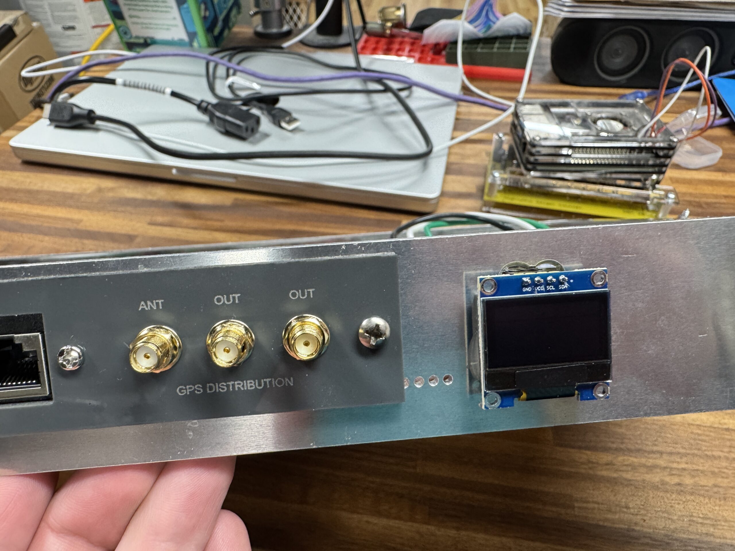
I don’t have redundant power feeds here at the house, so there’s only one power connection, and I have a number of other GPS-fed devices, so I put in one of my GPS antenna distribution amps, which makes it very easy to feed multiple receivers from the same antenna.
A little cheap OLED for displaying stats, and shove it all into a spare 1U box I had sitting around, and we’ve got a nice compact little setup.
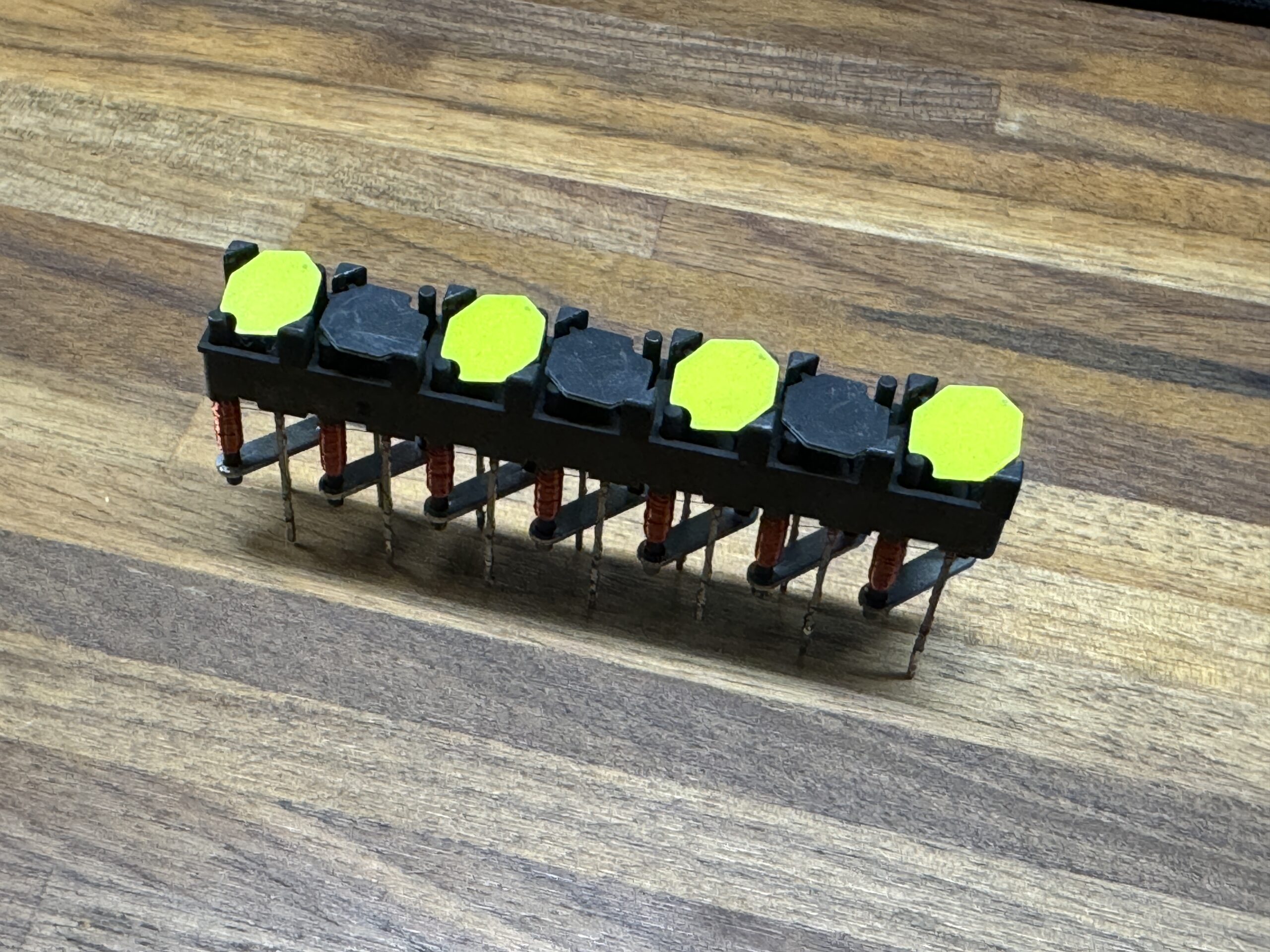
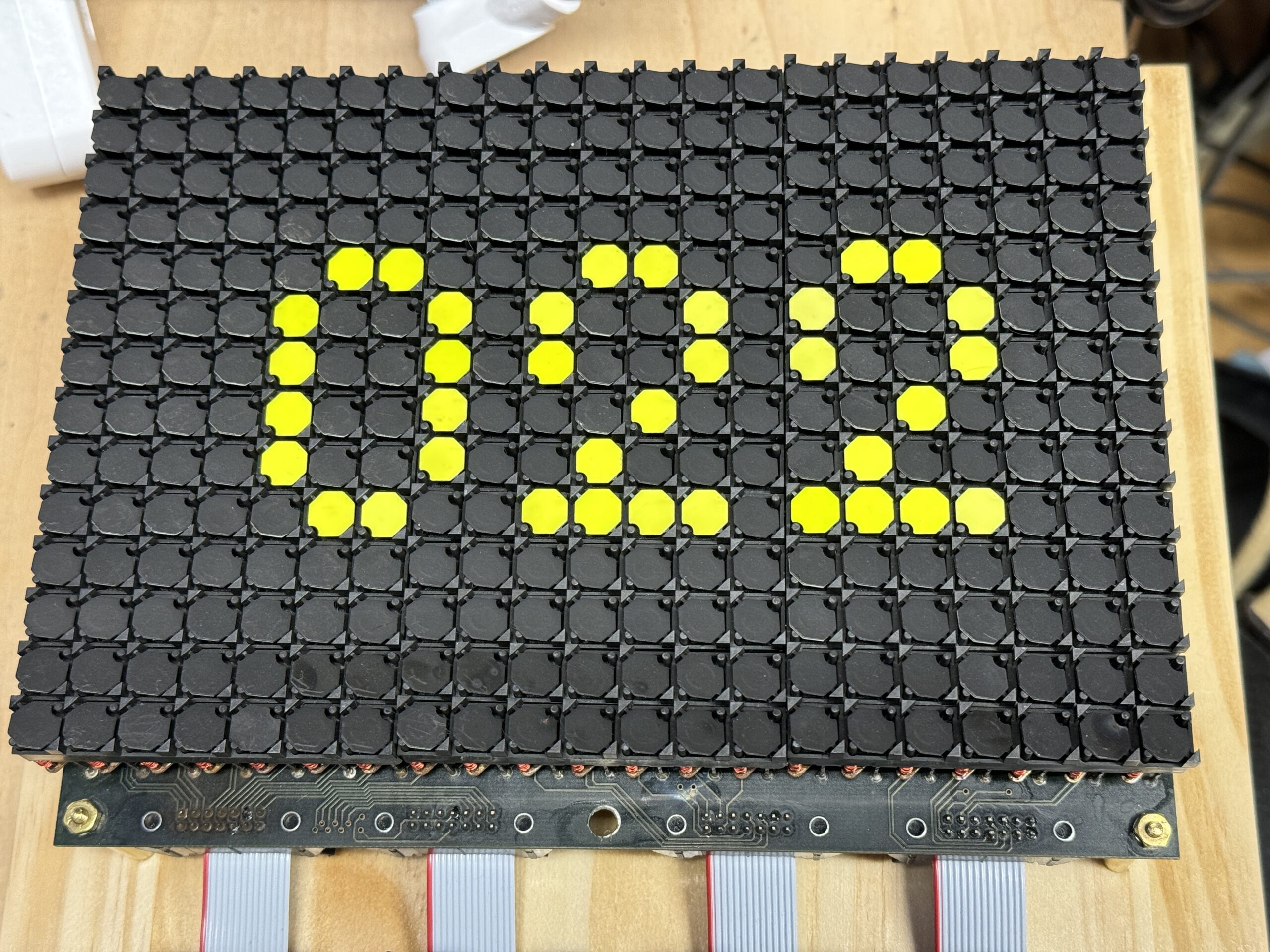
FlipDots are a very cool electromechanical display mechanism, and can offer significant power advantages, as they only consume power when changing state. These have been commonly used in roadside construction signs because they’re reliable, and can be easily powered from battery for an extended time next to the road.
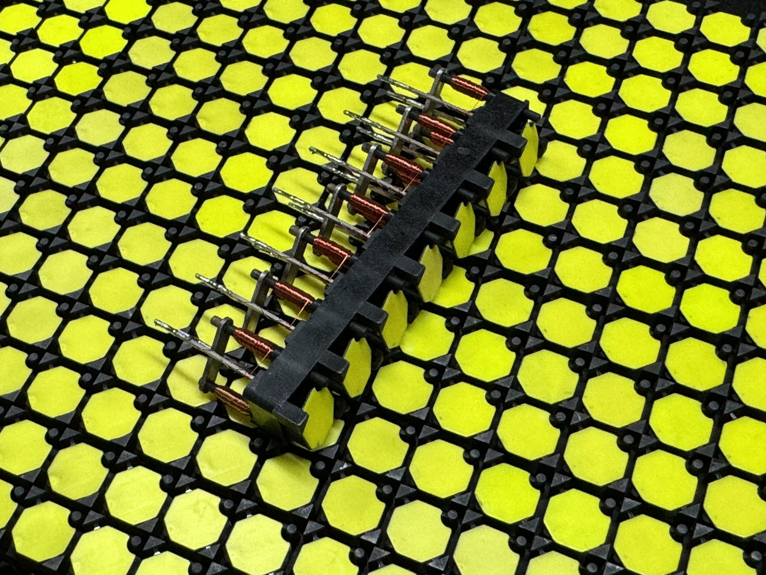
I found a panel (which I believe came from a display on a transit bus) on eBay, for a reasonable price, and wasn’t immediately sure what project I wanted to use it for, but needed to grab it.
One disadvantage of these, is that they’re a bit more complex to drive electrically. To flip a dot, a couple millisecond pulse needs to be applied in either positive or negative polarity. Additionally, though short, we need to ensure the pulse can be of reasonably high current. This is much like driving a DC motor with an H-bridge driver, but we have hundreds of dots. Adding an H-bridge for every dot would be extremely impractical.
With the use of diodes, we can arrange the control lines into groups of rows and columns, so we reduce the need for drivers down to a driver for each row, and for each column. For the full panel this reduces the number from 294 drivers for each dot, to 35 to cover each row and column.
I found some high current shift registers, one part is a high current source and the other a sink, so they’ll need to work in pairs. However we need to ensure that both are never on at the same time or you’ll end up in a ‘shoot-through’ condition where one driver is just feeding straight into the other and deliver potentially damaging current. Using some NAND logic, we can ensure that the enable control lines on the shift registers are never on at the same time.
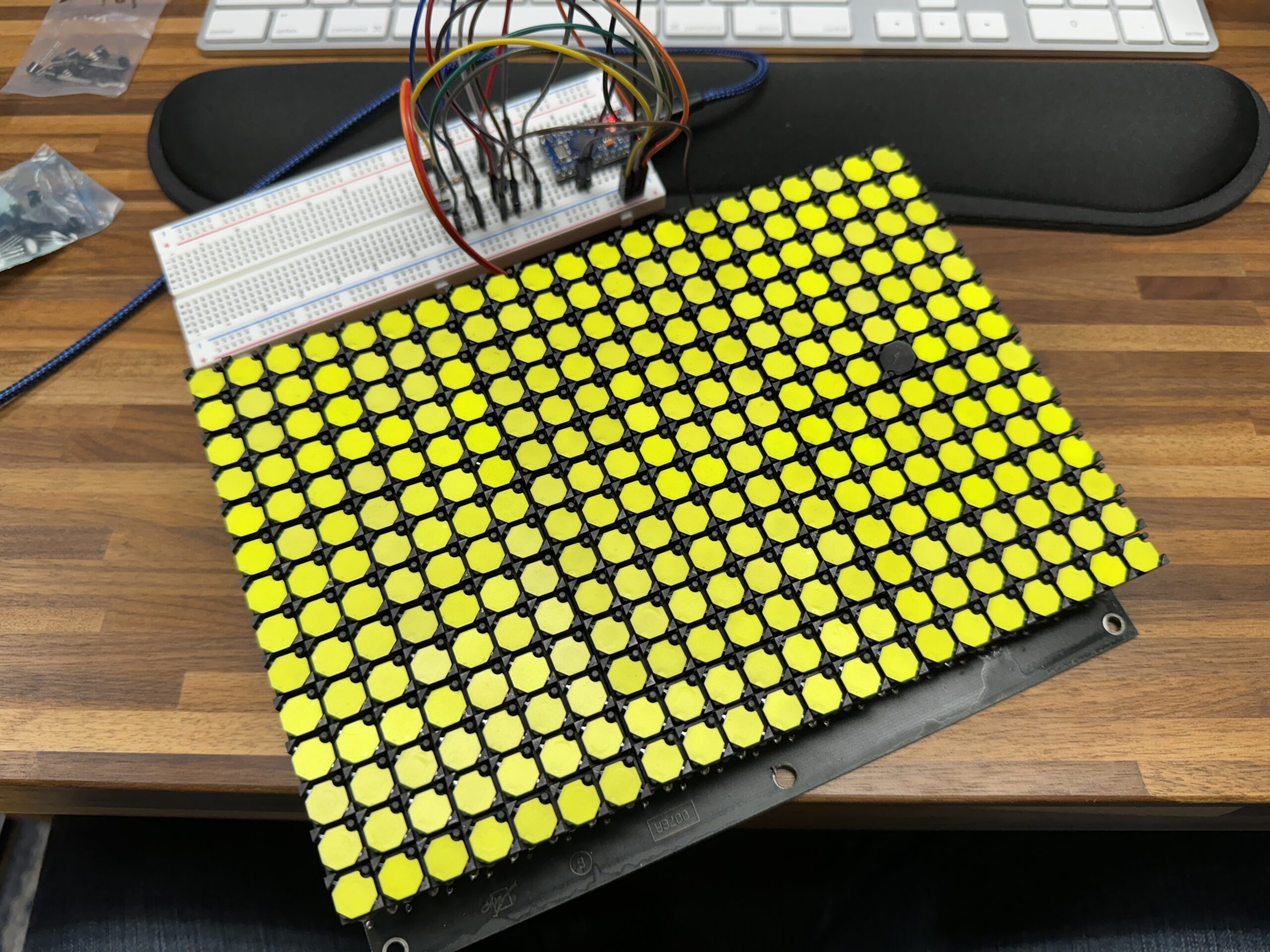
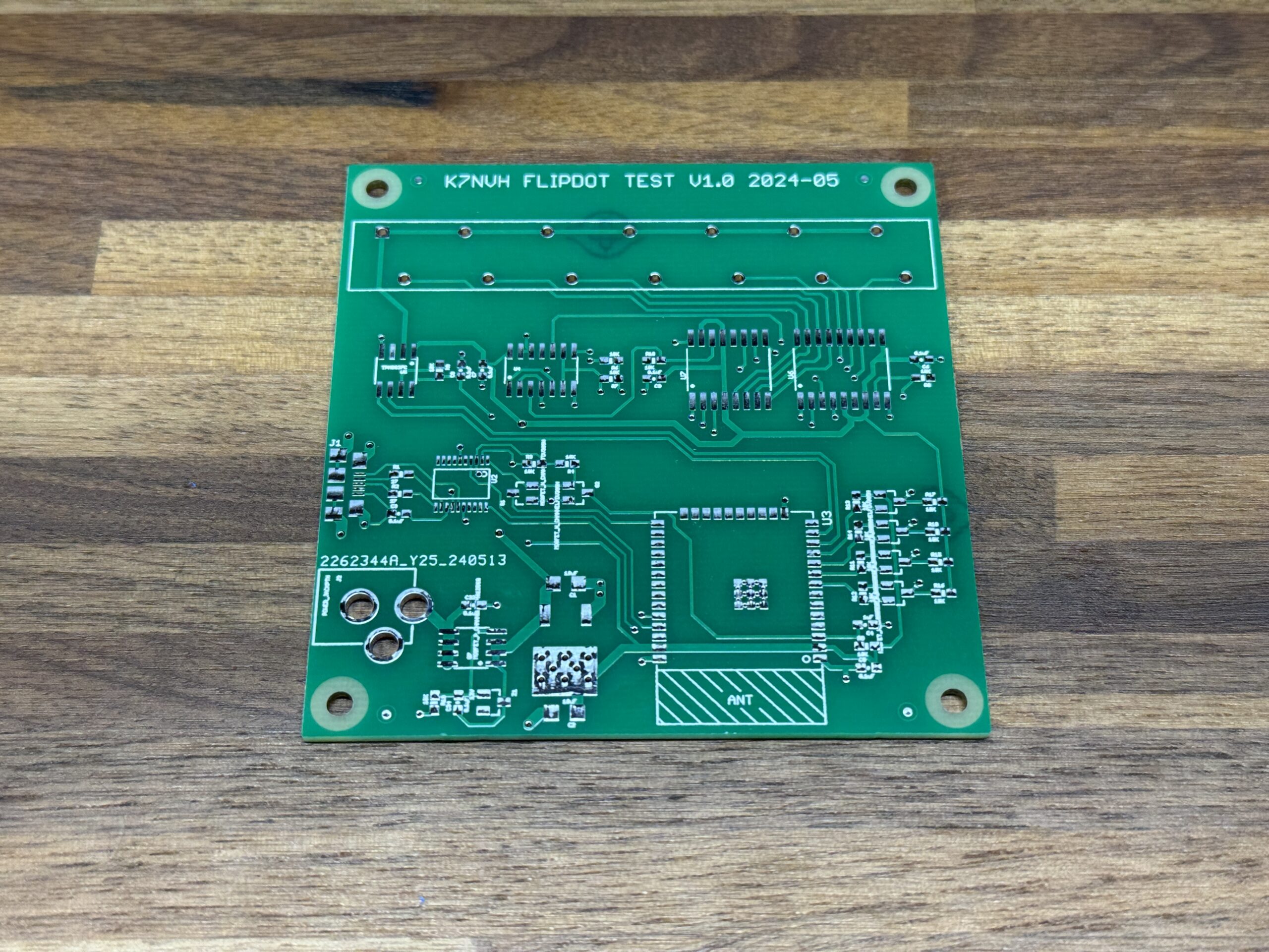
To test all this, I put together a small board to test a single row of dots.
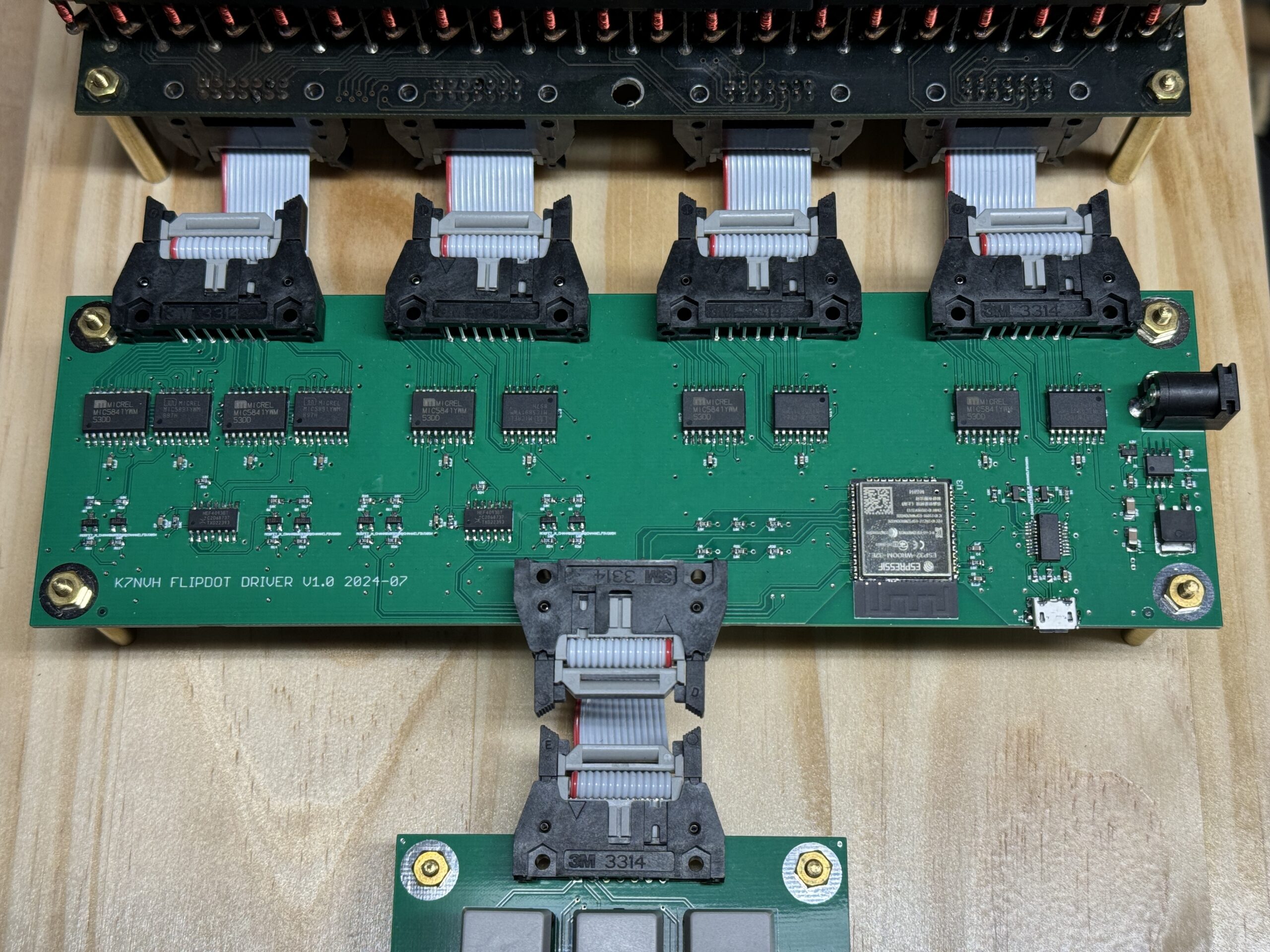
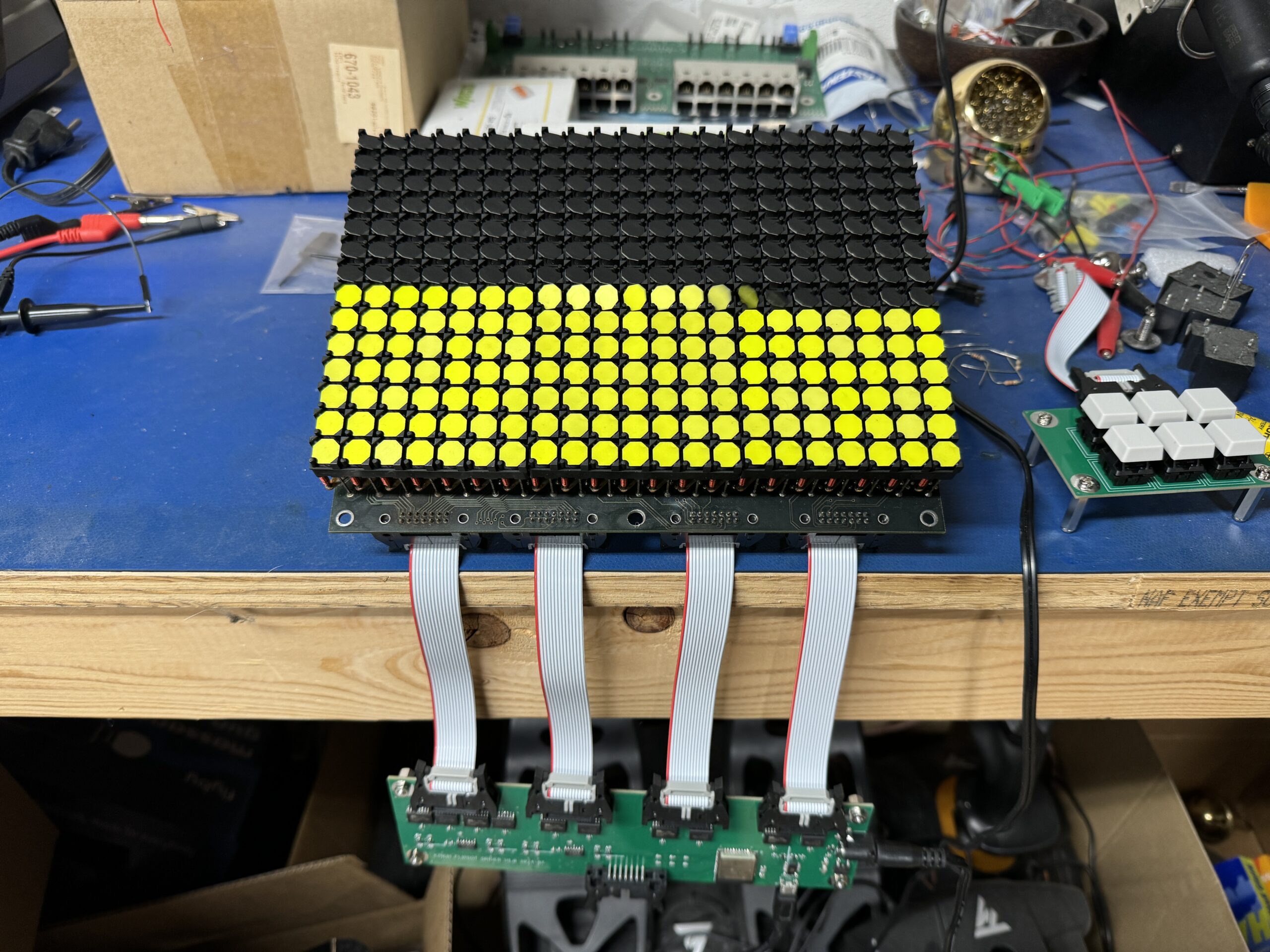
After a successful test platform, it was time to work on building up the full control board. Using the same building blocks we tested, with the high current shift registers, and the NAND protection logic, we set up the row and column groups.
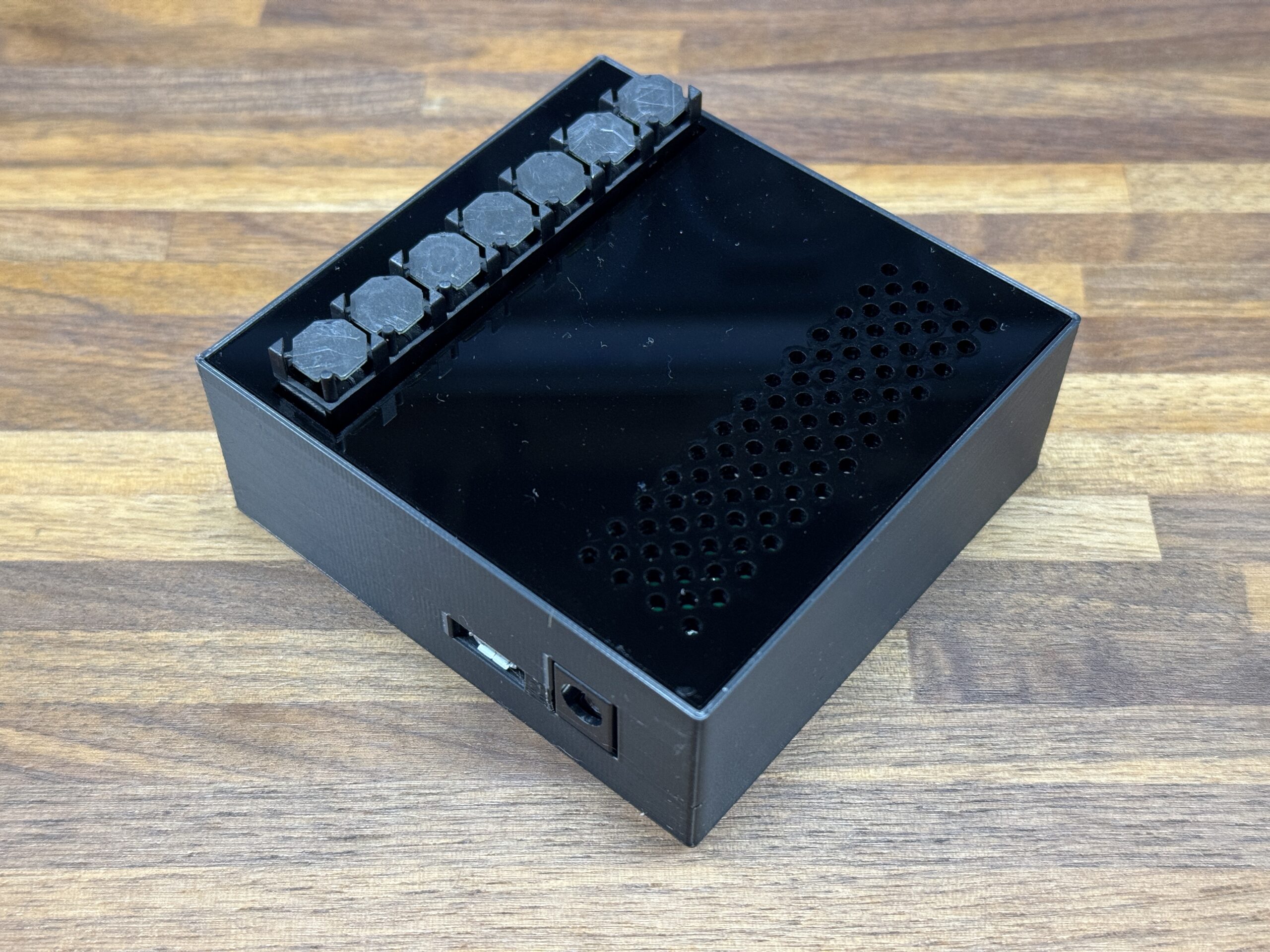
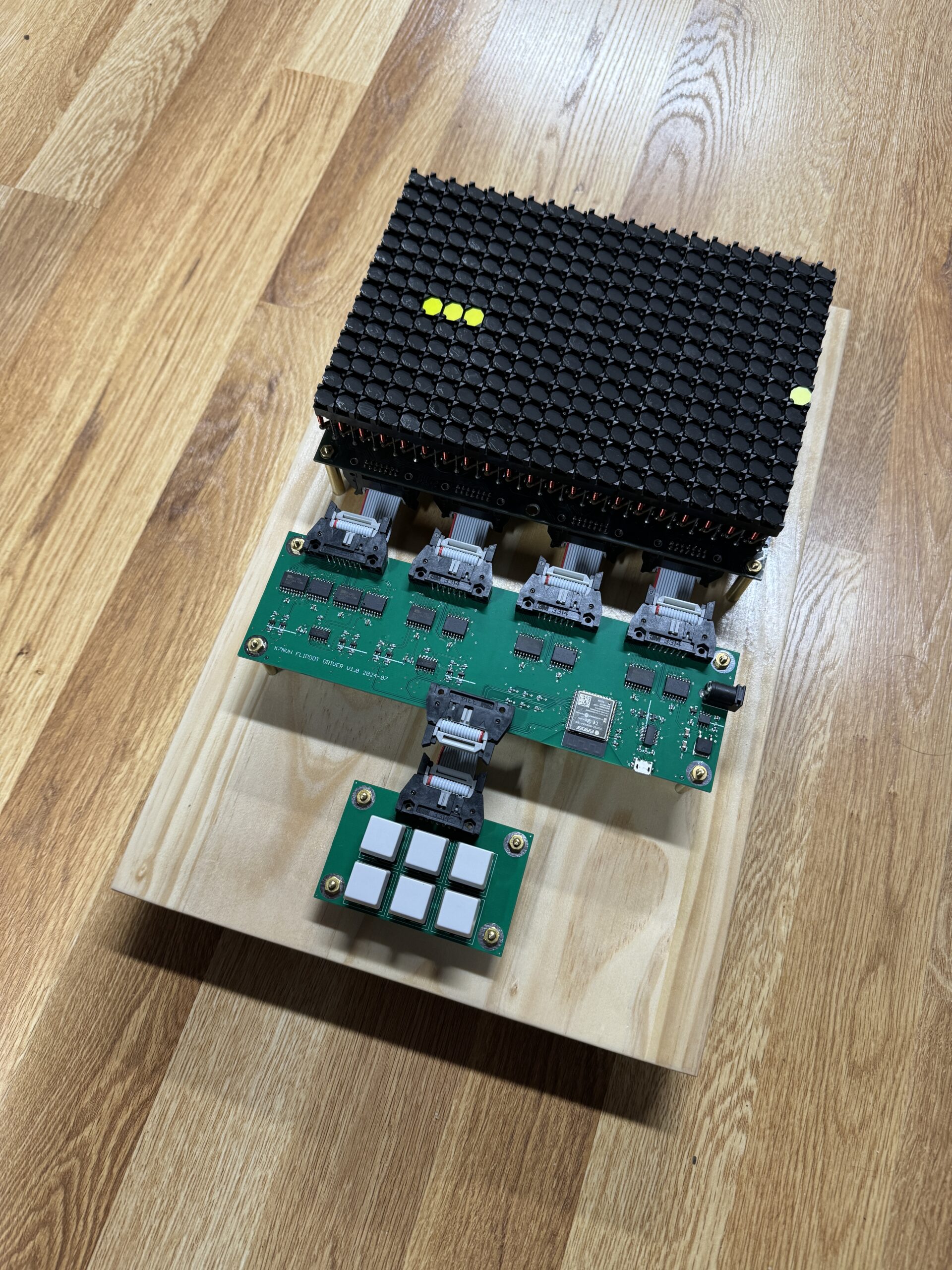
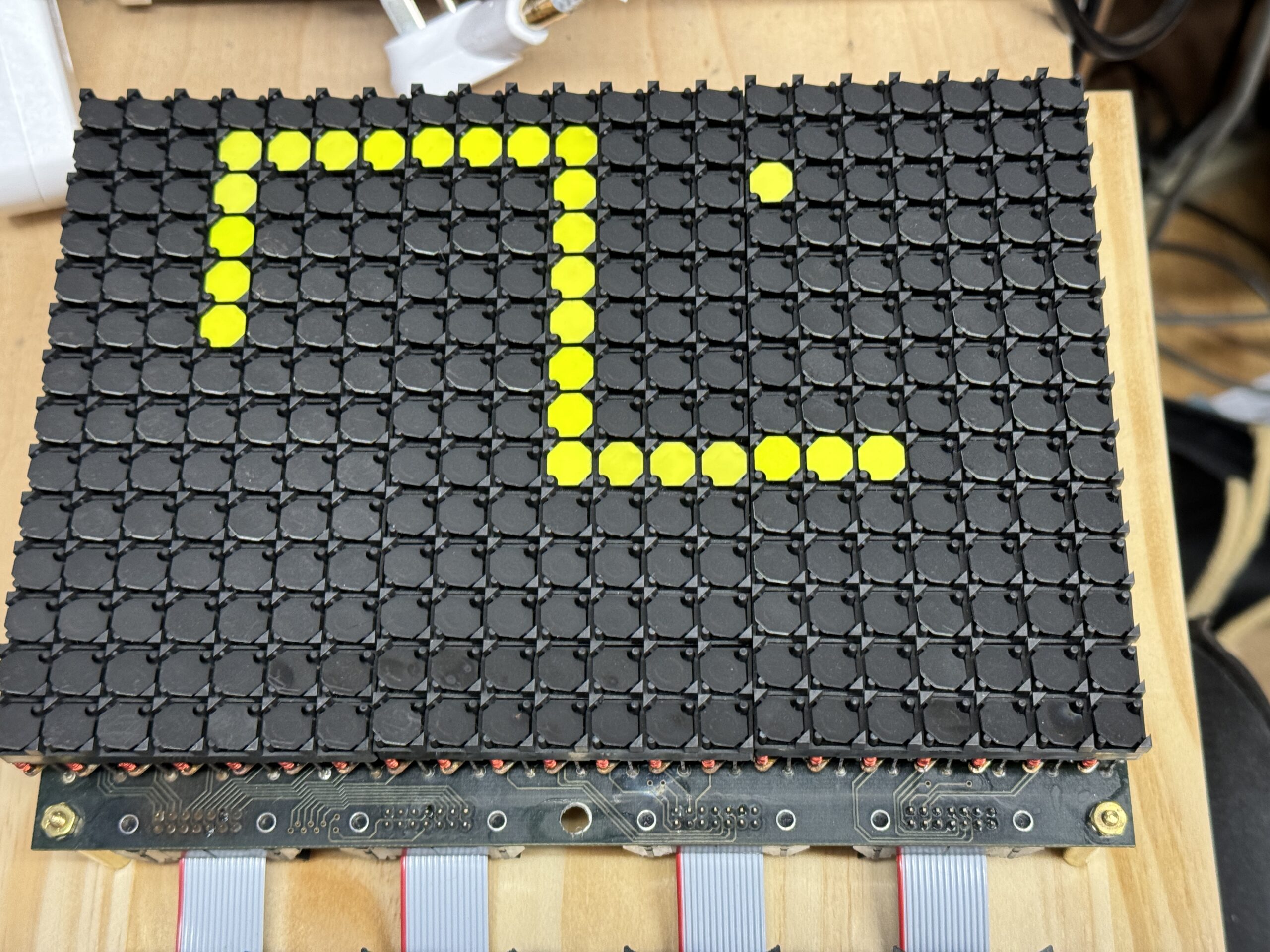
Finally, we can mount everything on a nice wooden base, and program up a classic nokia-style snake game. I might also work on adding game modes for Pong, or Breakout.
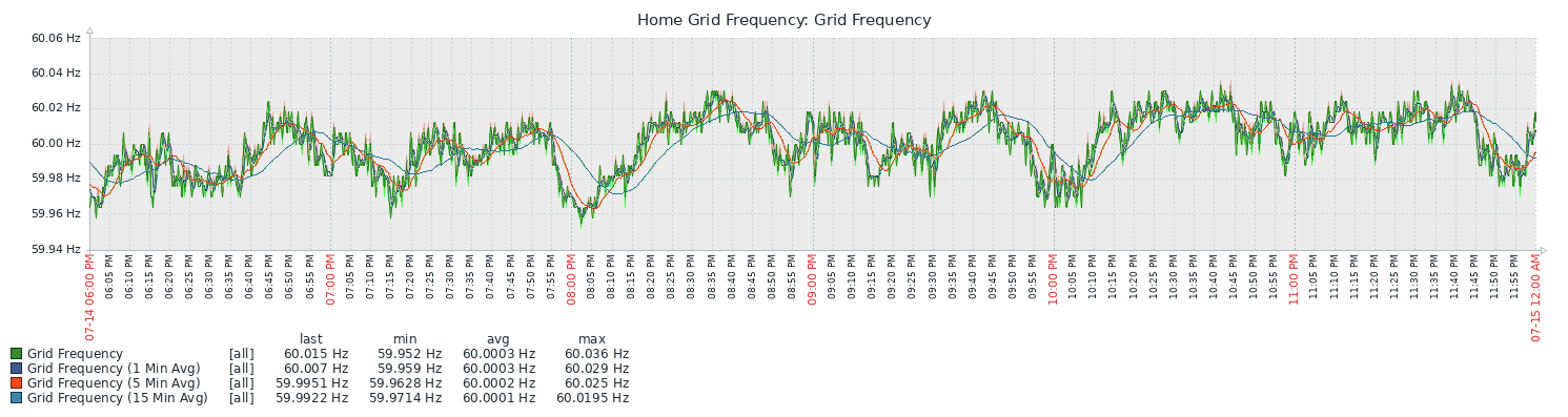
Some recent conversations with a friend regarding instability of the power grid, and particularly the issues they are facing regularly down in California, got me interested in setting up some logging of the local grid frequency.
Of course, there are wonderful resources already available, like FNET/GridEye at the University of Tennessee, but I tend to be inclined to want to make my own projects for the fun of it.
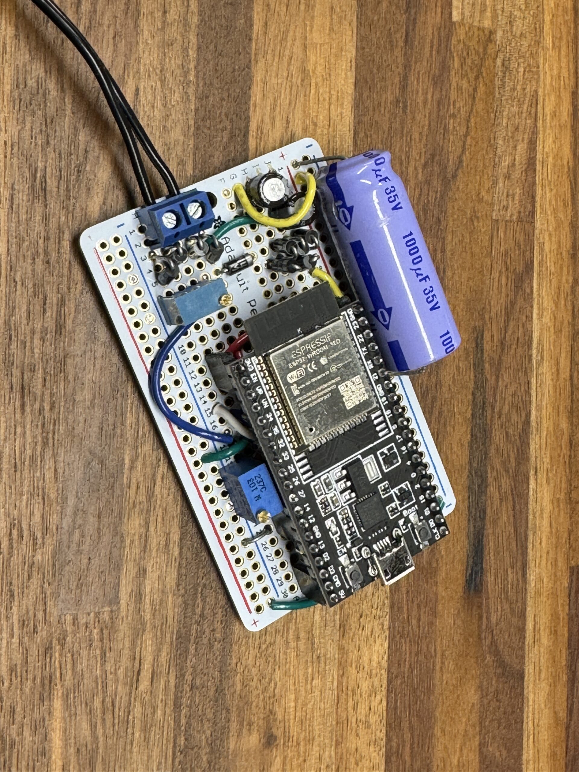
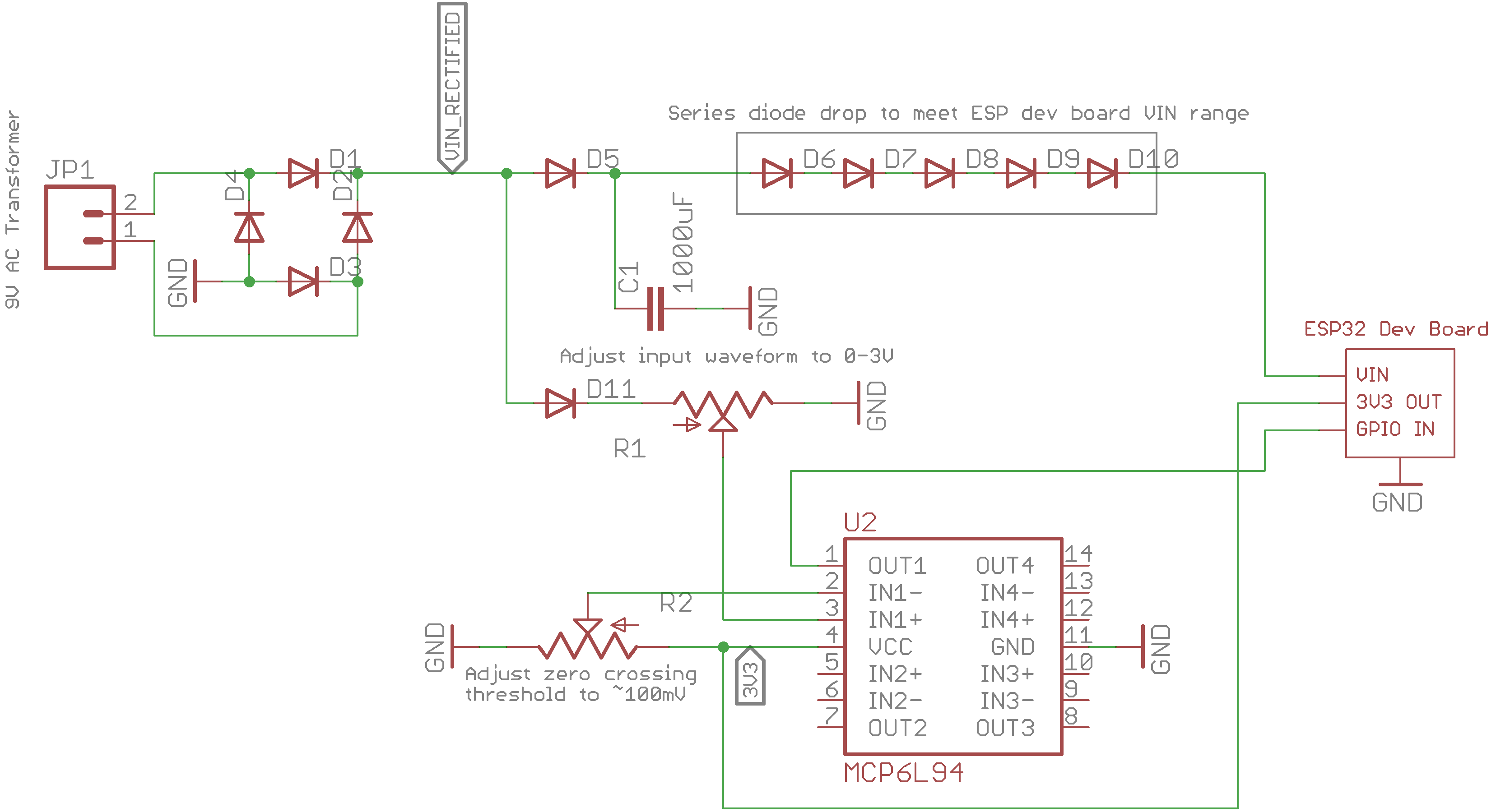
In contrast to many of my projects, which are cleanly built on custom circuit boards, this one is an example of classic throwing it together with the parts I had on-hand.
It’s an AC-AC wall wart transformer, feeding into a full bridge rectifier. Then it splits with a forward diode to a large capacitor and some series diodes to feed the VIN of the ESP32 dev board. The second path goes to a basic op-amp zero-crossing detector.
The ESP32 timestamps the zero-crossing pulses, averages them over a few different time windows, and outputs frequency measurements. The measurements get uploaded over wifi to my central data-collection system and I generate graphs of the data.
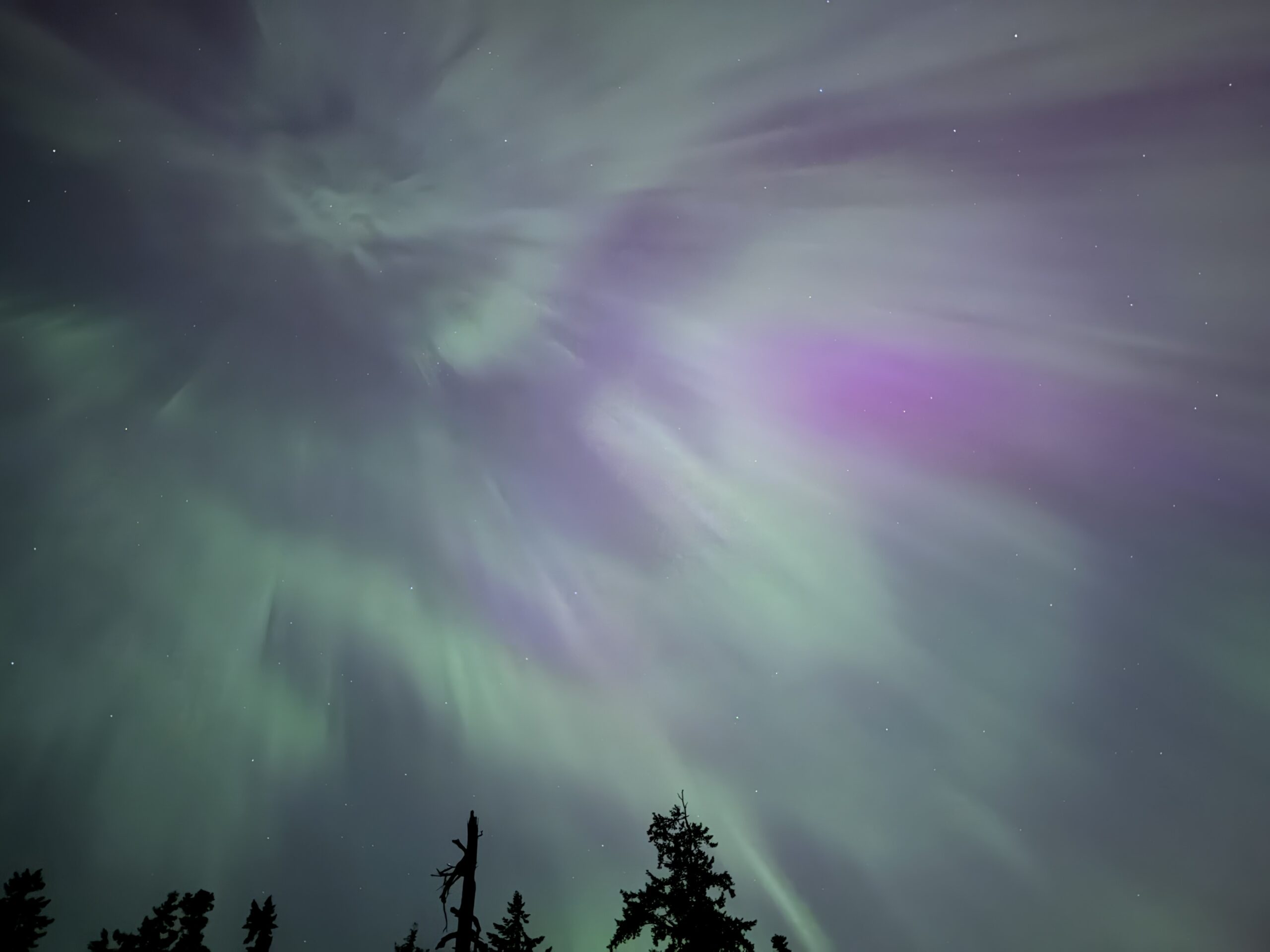
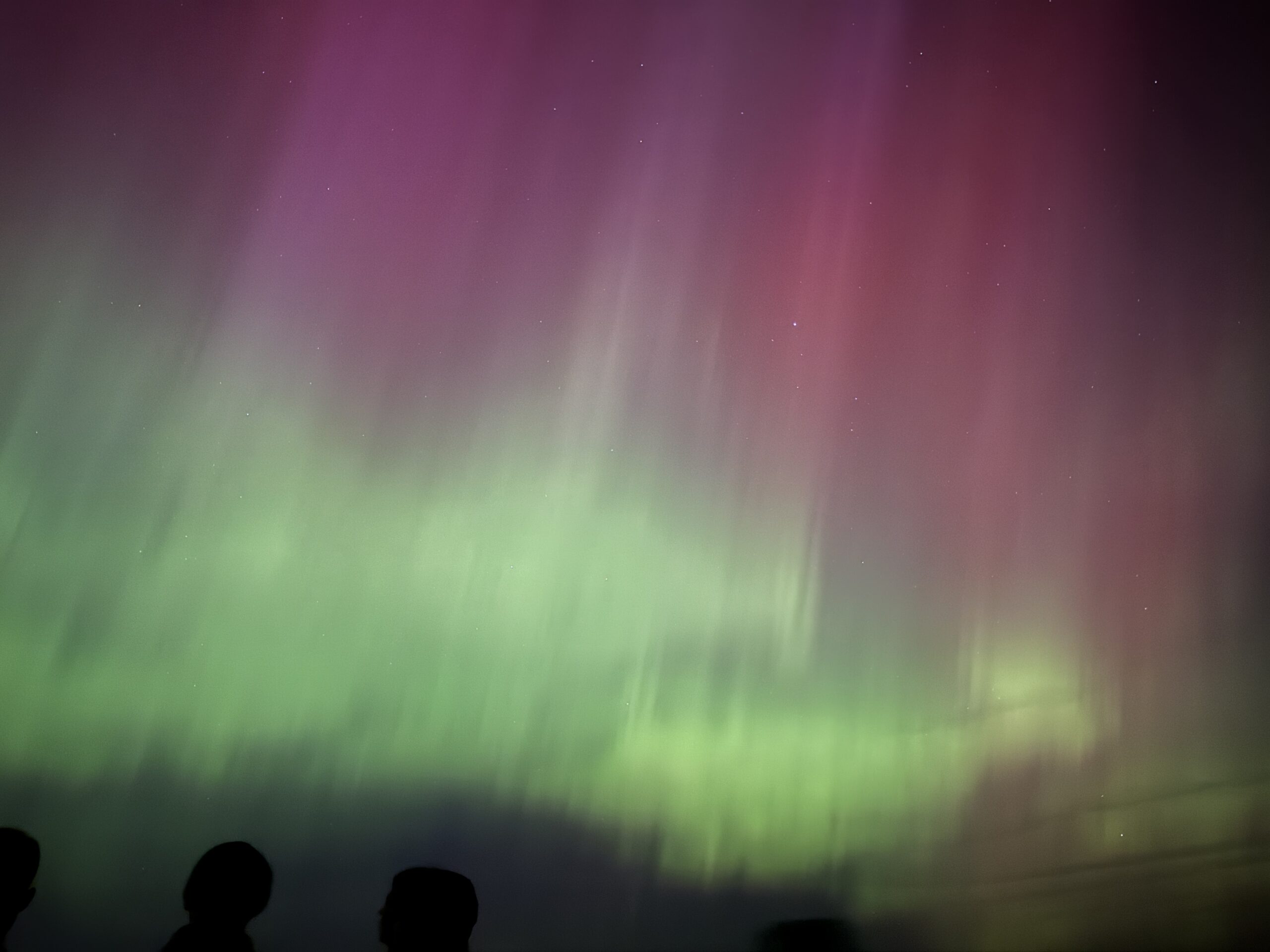
With the anticipated Aurora being visible, I decided to head out to a dark area on Camano Island to try and get a better view. On initial arrival, I really couldn’t see much, but over the course of the evening, we ended up getting quite a good show. Here’s some photos I took just on my phone.
I also took the footage from a camera on one of HamWAN’s mountain-top radio sites, and made a timelapse of the evening. Some really incredible action about 2 minutes in.
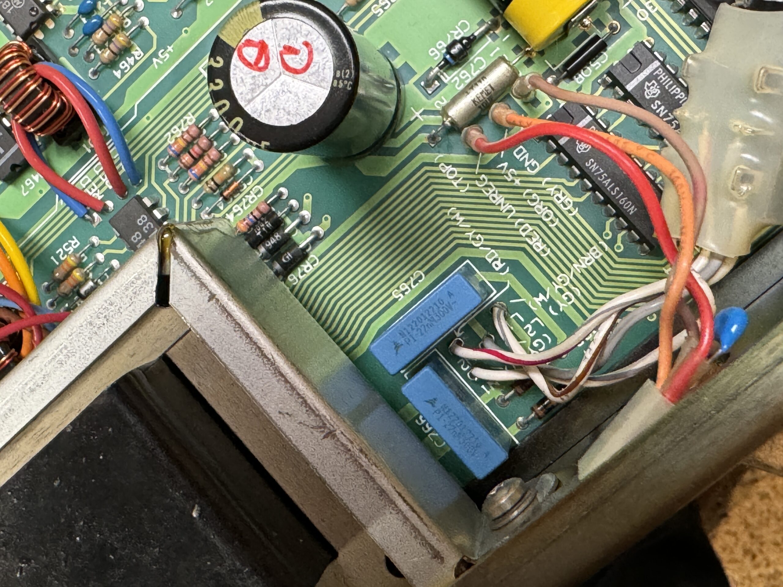
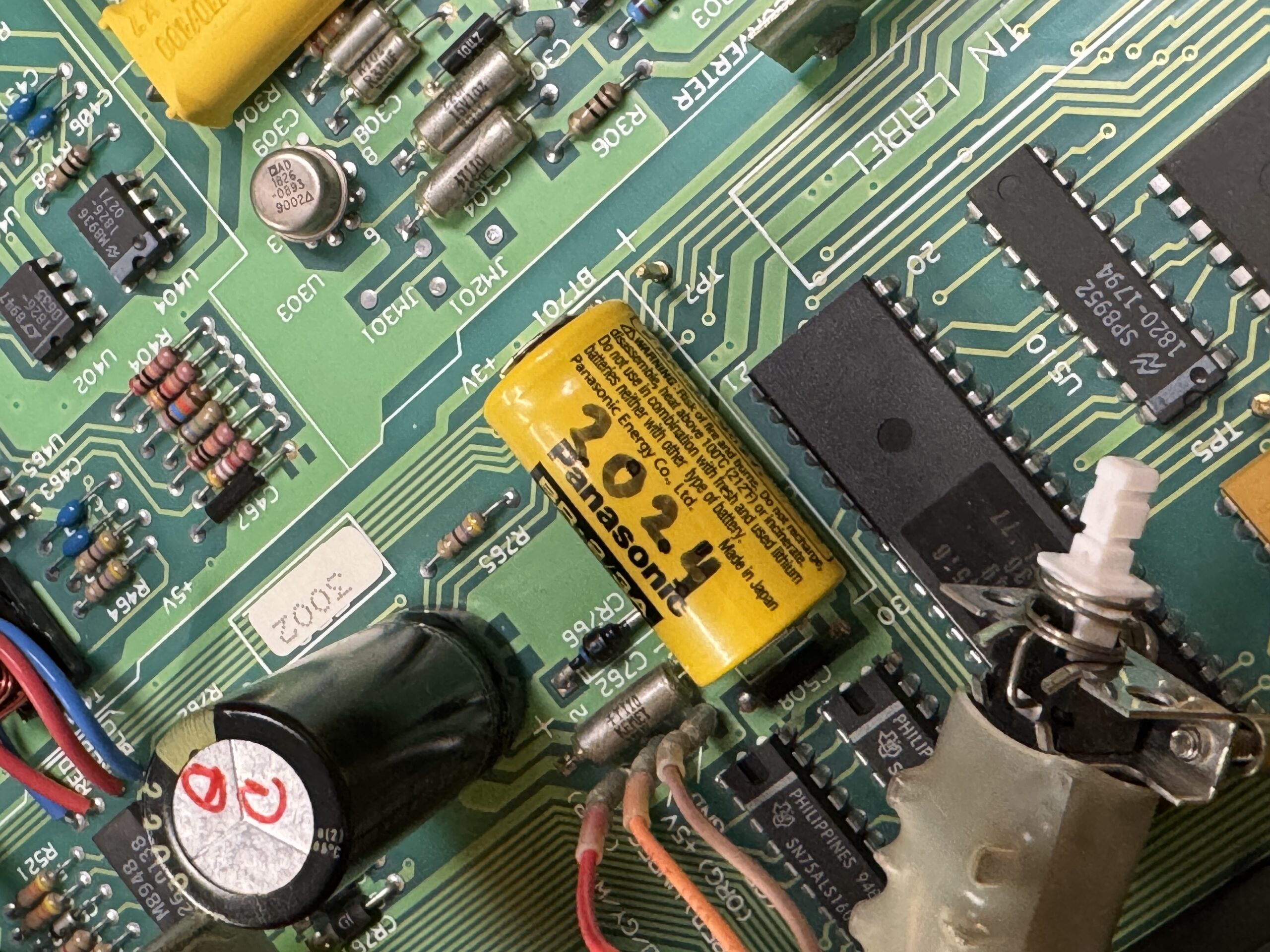
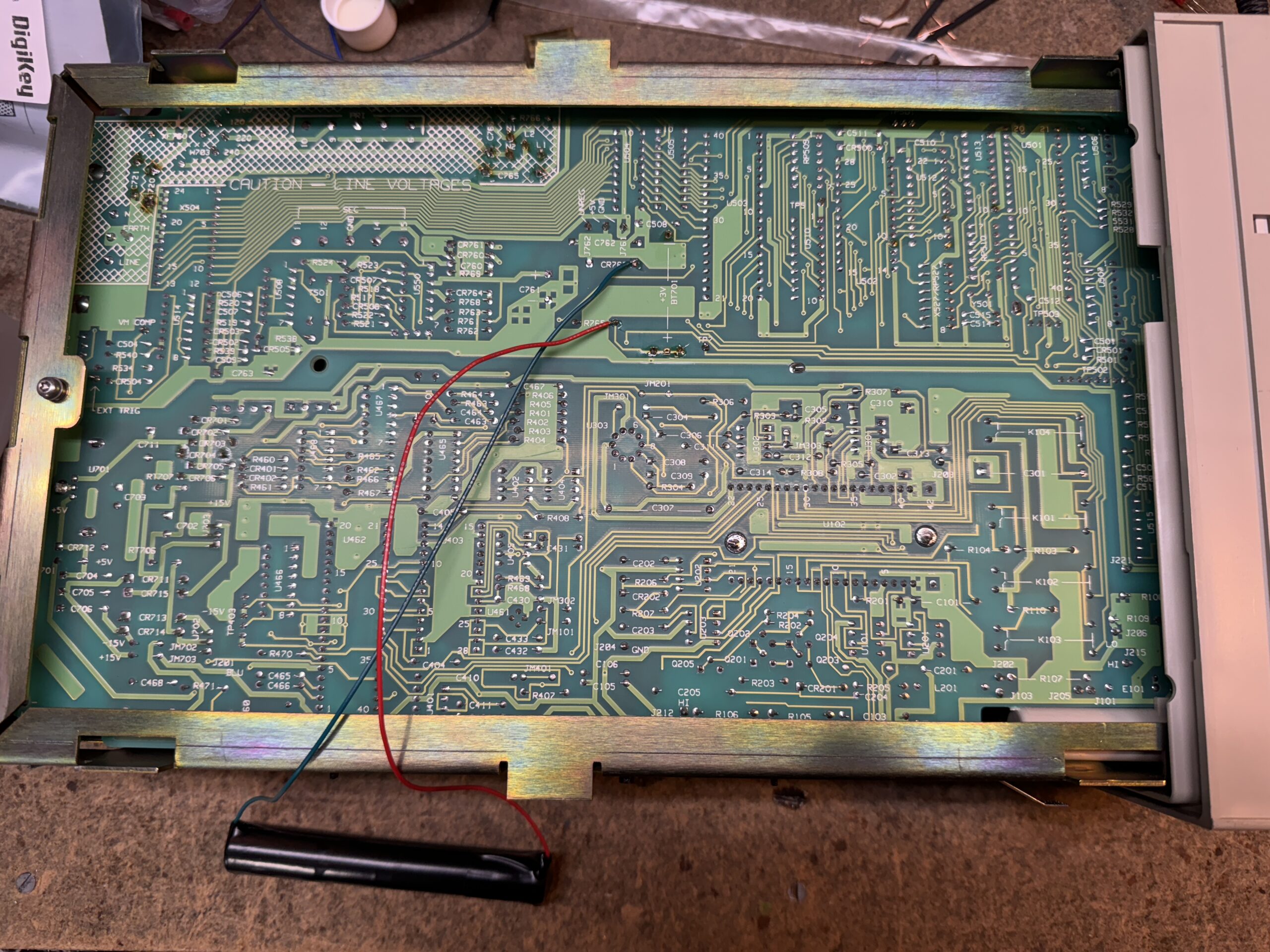
I’ll start with noting that these repairs on the HP 3478A (and many other older HP instruments) are well documented amongst the community. I mostly referenced the excellent write-up here by Tom.
I mostly followed the procedure described, I backed up the SRAM via querying the contents over GPIB, wired in a pair of AA batteries to keep the SRAM active, and replaced the lithium cell. After which, followed it up with replacing the old RIFA caps, which are infamous, and as expected, had cracked in my instrument.