Testing Self Clinching Standoffs

I’ve recently been looking at better ways to mount a PCB inside a metal enclosure. Primarily I’m interested in ways that don’t require screws protruding from the bottom.

I found these self clinching standoffs on Fastenal’s web site, and figured I’d give them a try. Normally they’re installed using an automated press, but I gave it a shot with the cheap Harbor Freight press I’ve got.

Apologies for the vertical format video. Handling the camera, the metal, and the press at the same time was a bit unwieldy.

Posted in Random | Leave a comment

Generator Box

A little while ago I picked up a generator for use in power outages to keep things like the fridge and computer equipment going in the case of an outage that’s lasting more than a few hours.

While, one of the fancy super quiet Honda generators would be great, the cost meant that I got a more conventional generator, that’s just a bit louder. While it’s not horrendously loud, quieting it as much as possible is still a benefit.

A common means to do this is by building a sound dampening box, so that’s what I did!

I still want to add some sound foam on the inside to dampen things a bit more, but for now it’s a plywood box that gets placed over the generator, with baffles to reduce the sound output.

Placed in the back yard, with the box over it, exhaust side facing towards the laurels, the sound was reduced by a bit more than half (4dB). With additional damping, I think there’s room for improvement.

Posted in Projects, Weather | Leave a comment

Coin Teardown

Some time ago I backed a project called Coin that aimed to make a single card that could replace all of your other credit/debit cards. I thought the idea of having all my cards available without having to make room for them in my wallet was a neat idea.

After some time, their team got the device together and shipped out, and I got to use it for myself. I used it for about a month, and quickly came to the conclusion, that it couldn’t replace all my cards, primarily because it didn’t work reliably.

Coin is a bit of tech that tries to digitally pretend to be your selected card as it’s pulled through the stripe reader. It’s a really neat trick, and if it were another industry, it might have worked out better, but when it comes to paying for things, it *HAS* to work, *EVERY* time.

Coin ended up working for me about 75% of the time, which admittedly was pretty cool, but it wasn’t enough of the time that I could pull my other cards out of my wallet. I still needed to be 100% sure I could pay for things, and needing to keep my other cards in my wallet anyway as backup destroyed Coin’s usefulness to me.

Since those days, Coin has sat on my desk, collecting dust, until recently… as you would expect, I finally decided to tear it apart and see what made it tick.
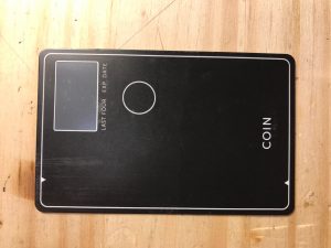
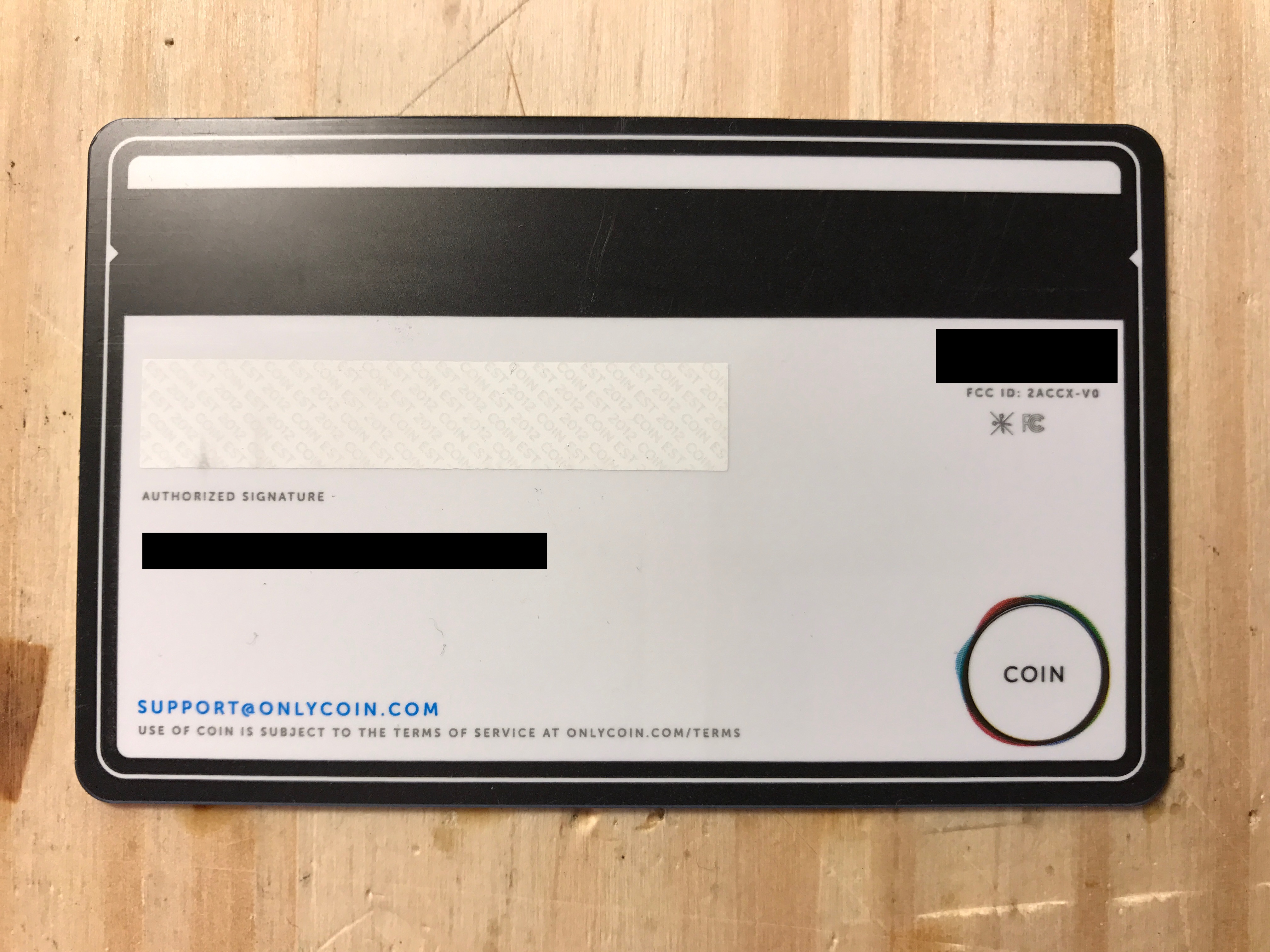
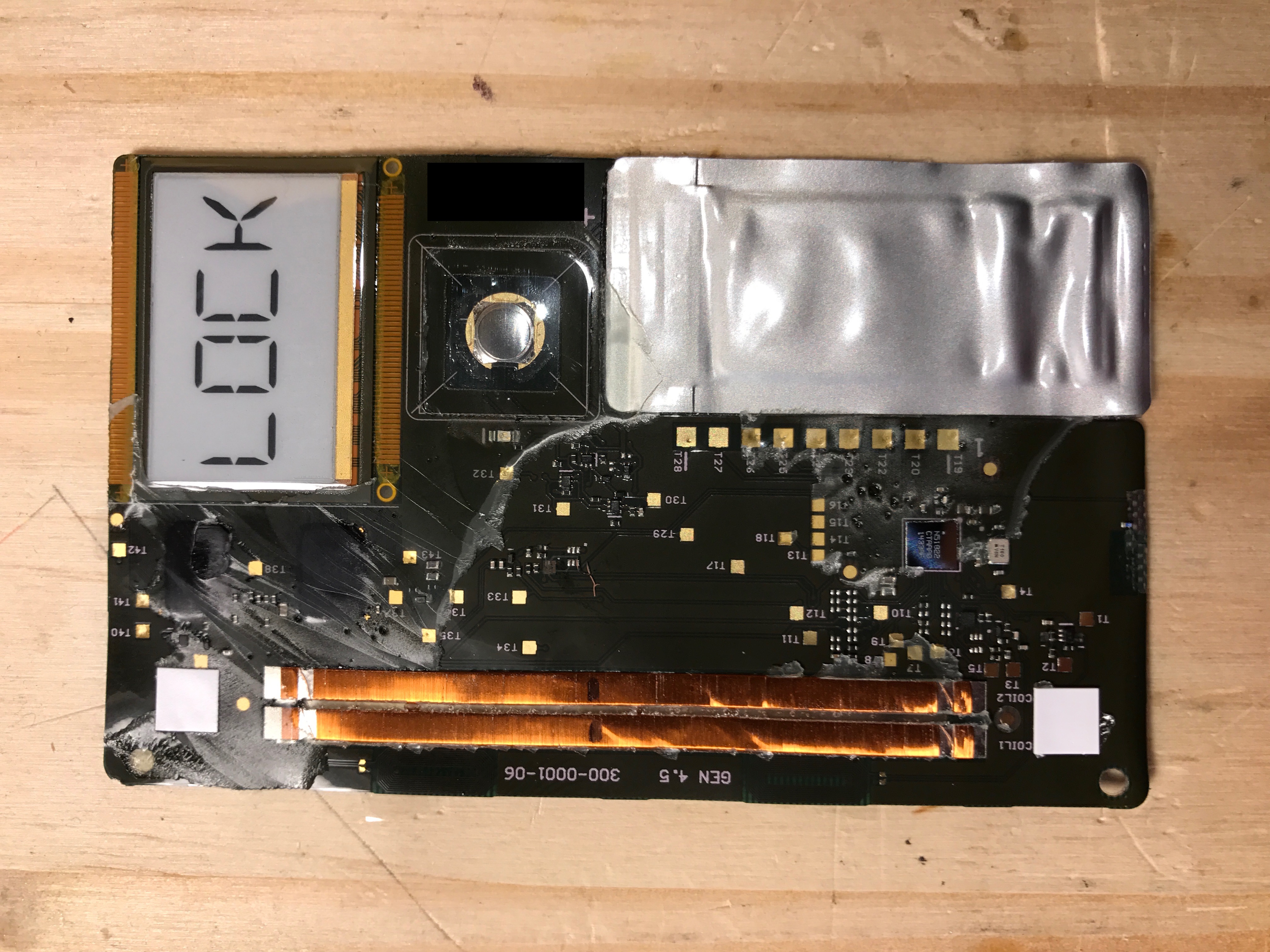
Coin – Pre teardown

img_4708 img_4710_edited

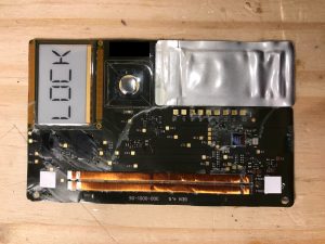
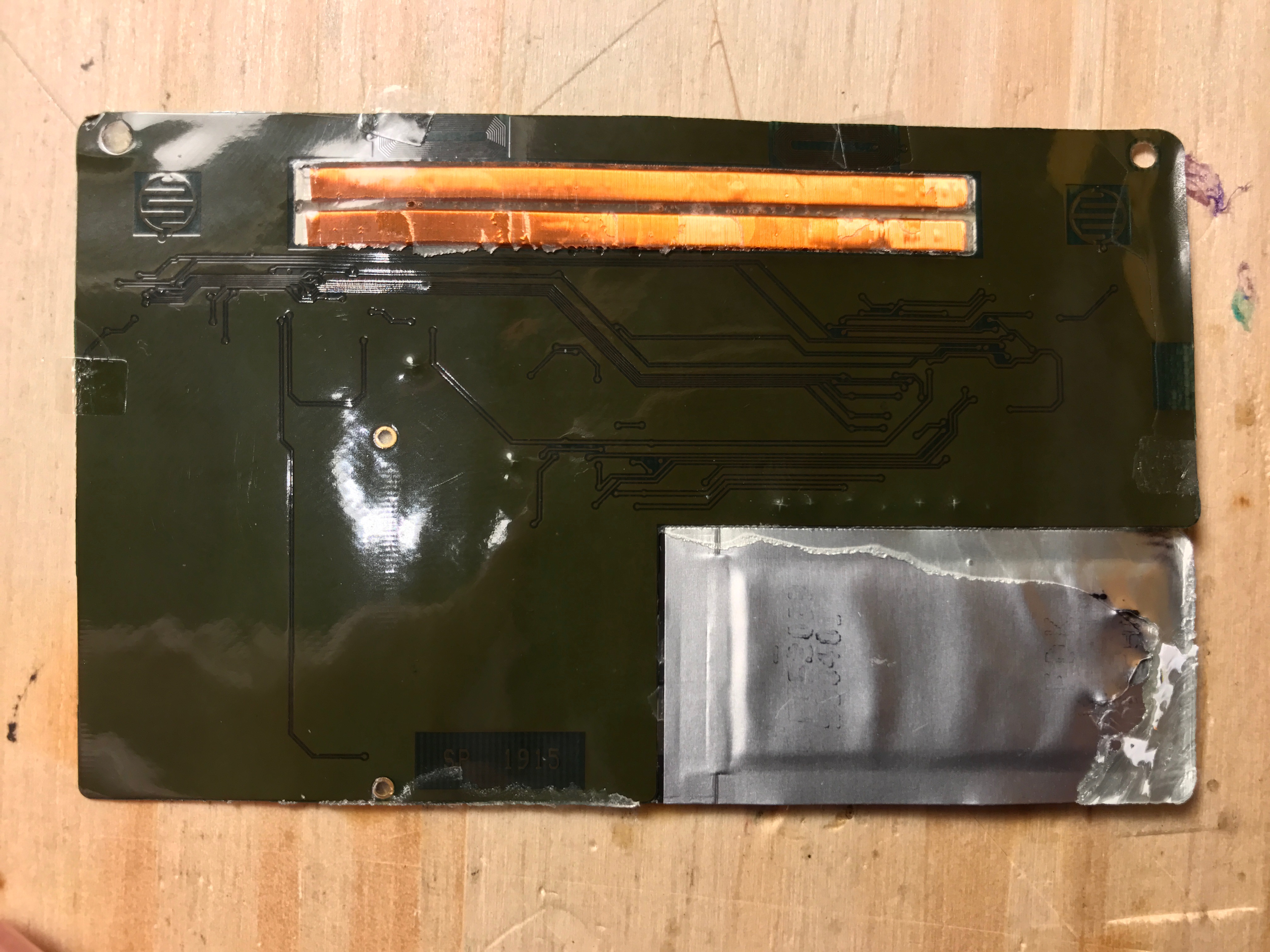
The PCB is paper thin, and glued between the plastic front and back. A bit of heat and effort softened the glue and exposed the insides.

On the top, you can see the display, button, and all the components, in addition to the 3V lithium primary cell powering the device (No it’s not rechargeable, but lasts a long long time), as well as the magstripe coils.

img_4713_edited img_4717

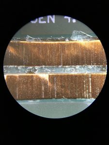
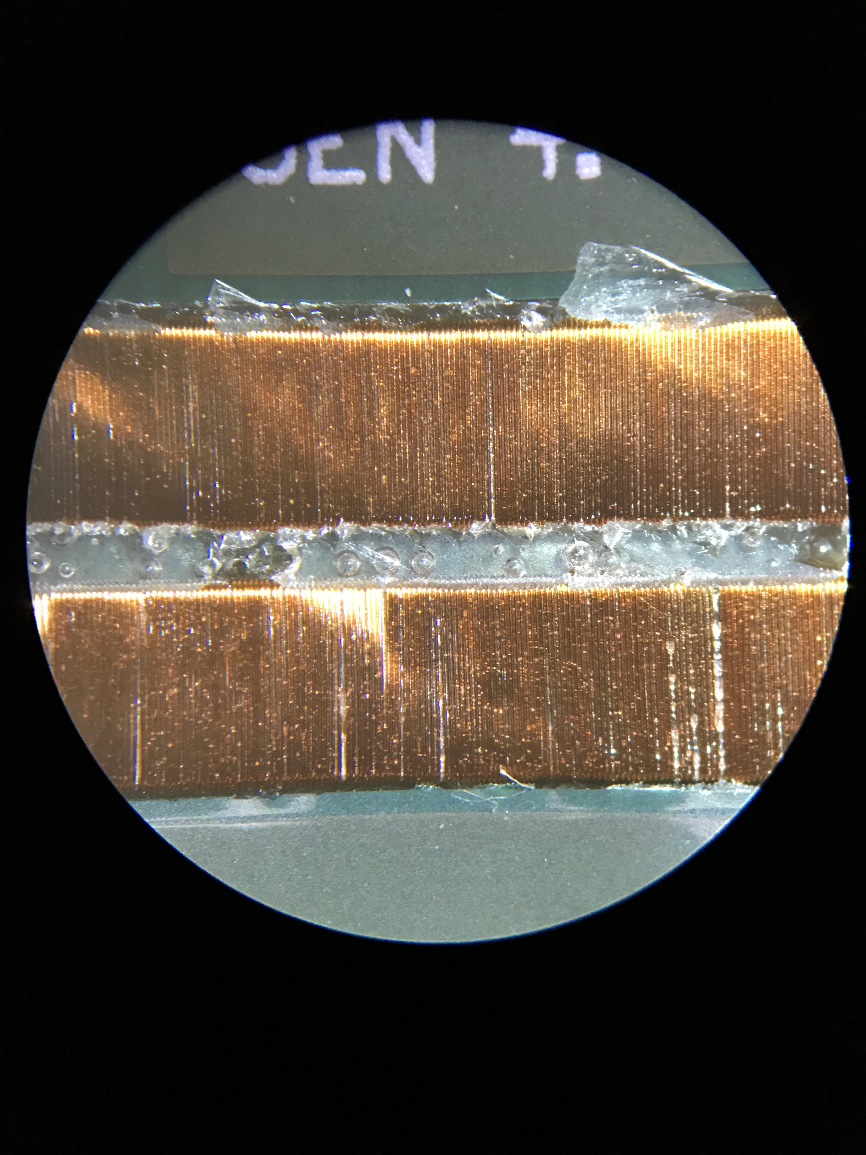
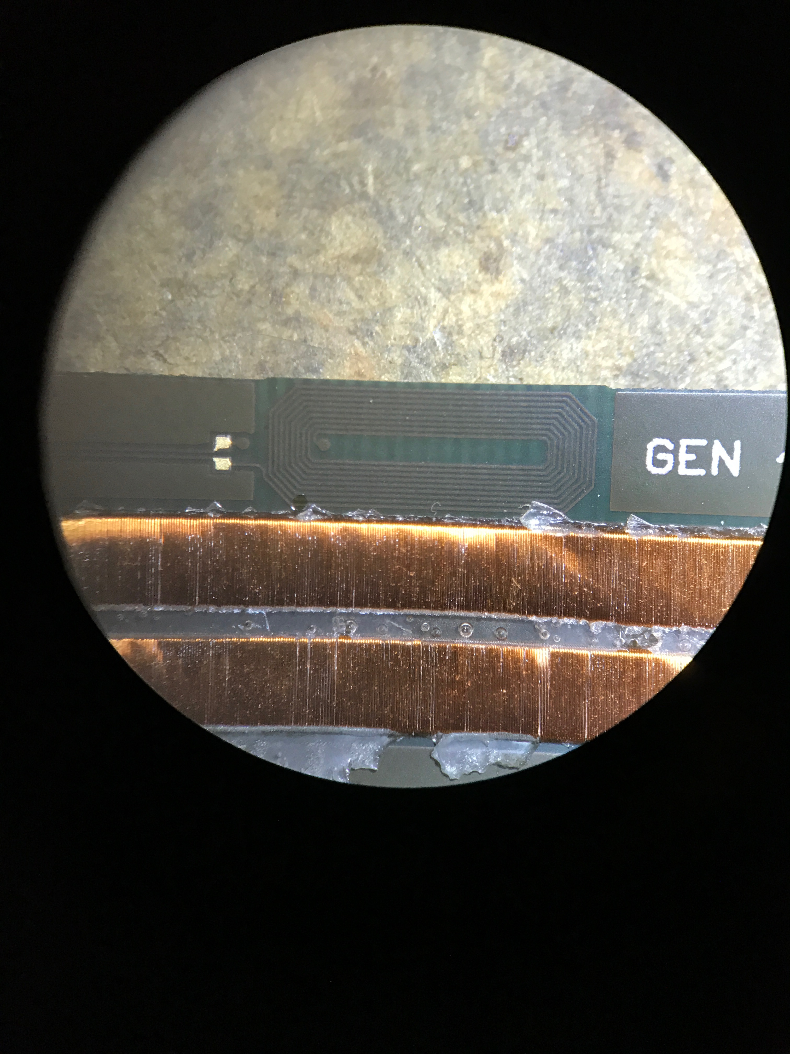
I put it under my microscope to get a closer look at some of the details. Here are the magstripe coils. Looks like it’s just one long coil, not a bunch of individual coils representing the data, so that means Coin is just playing back the bits in sequence like a recording. In theory this would work even if Coin was sitting still in the reader.

img_4721

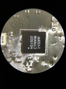
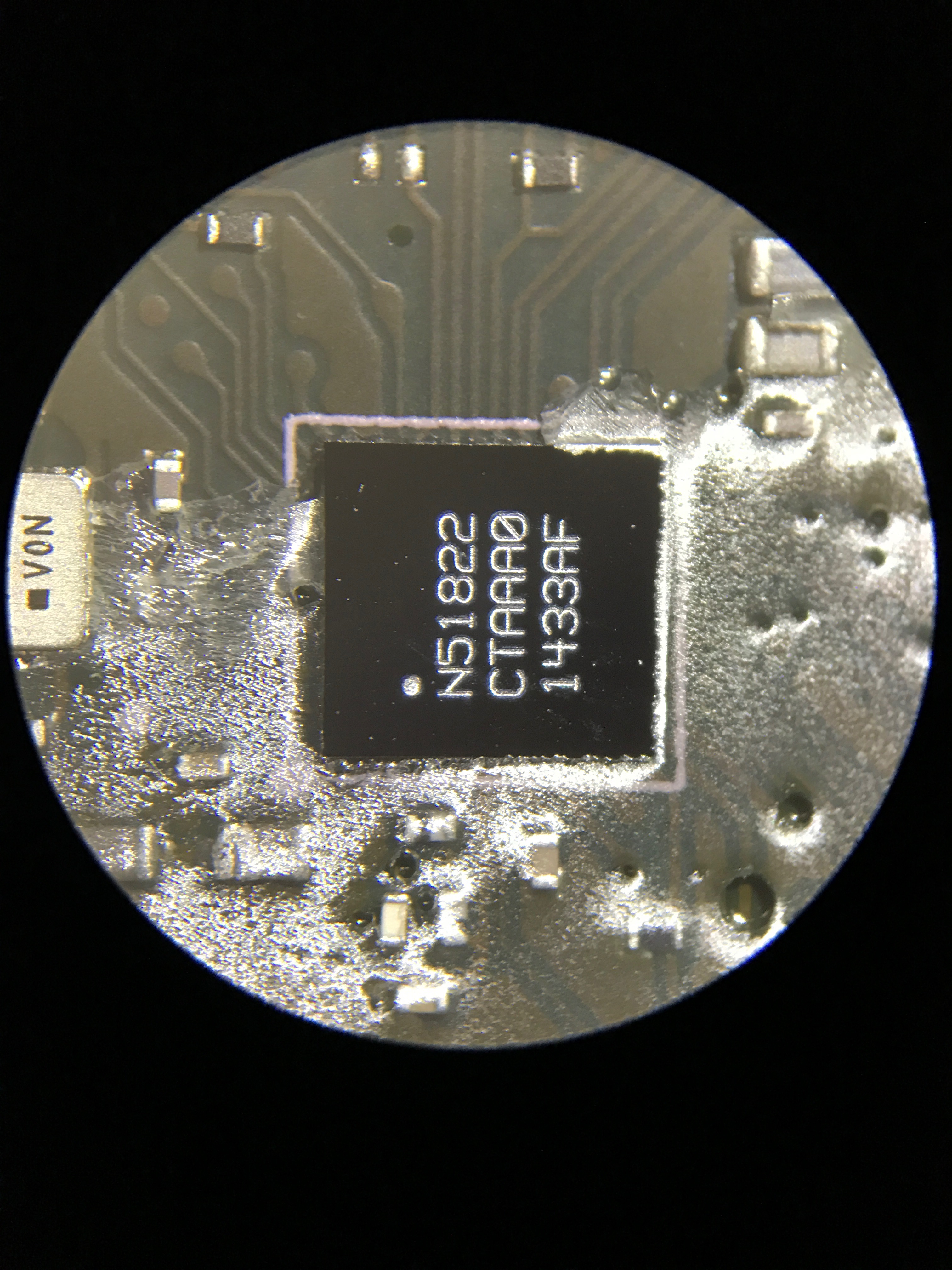
This looks to be the main microcontroller, It’s a Nordic Semiconductor nRF51822 which is specifically designed for very low power applications, and bluetooth connectivity (which Coin uses to talk to your phone.)

img_4722

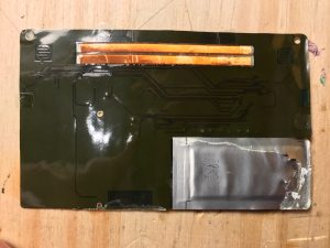
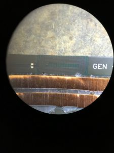
Here we see what I’m guessing is one of the two Bluetooth antennas, stuck out on the edge of the PCB, and the ground plane pulled away a bit.

img_4724

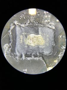
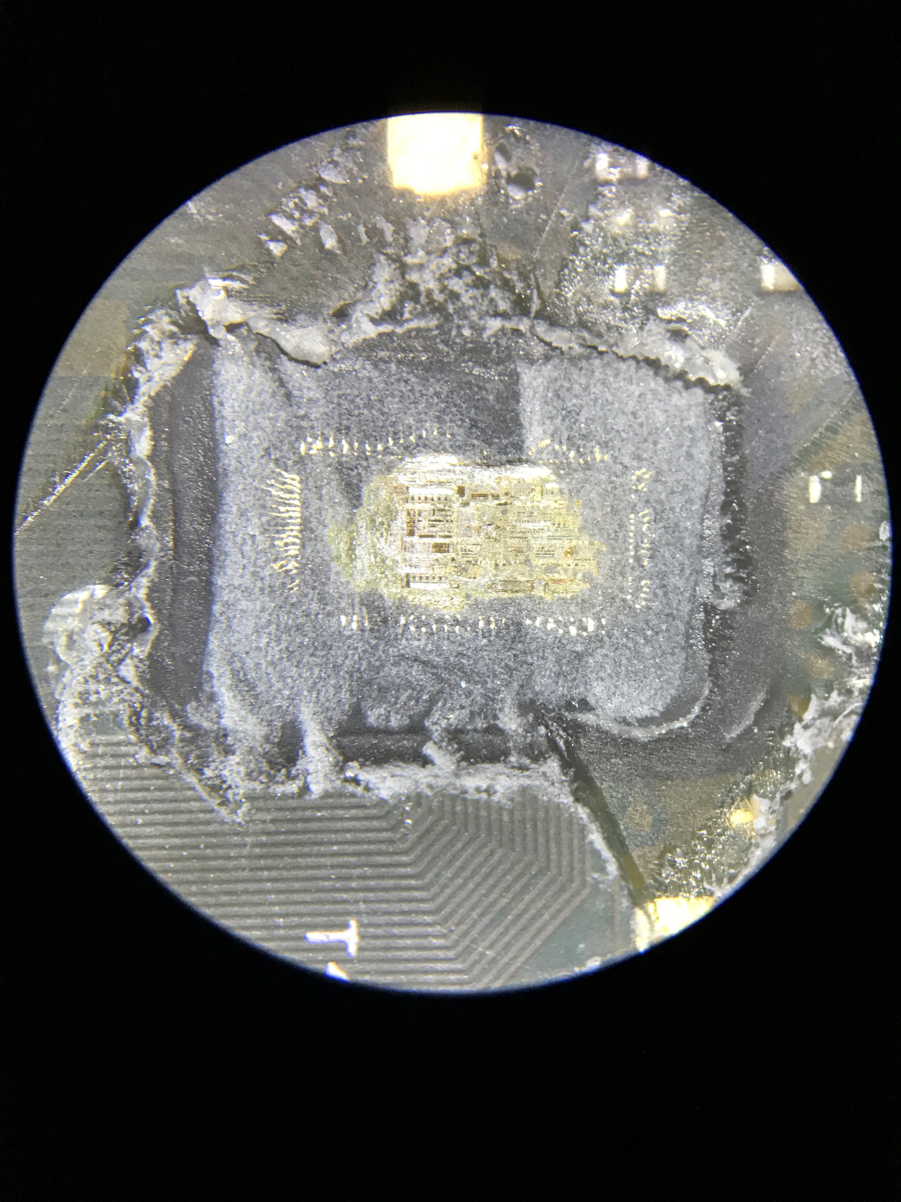
This used to be a Chip-on-Board device before I destroyed it by scraping the black encapsulant off with a knife. You can see the die in the middle, and the gold bond wires around the outside of the die that connect it to the PCB traces. Given the proximity, and where the traces go, I’m betting this is a display driver.

img_4726

So, in short, a neat bit of tech, a few core components, shoved into a REALLY thin package, and I’m sure a TON of software development and testing time to get it to work as well as it did. Unfortunately it just wasn’t working well enough to be useful to me.

Also, you can see some photos of what I presume is a pre-production device in this FCC filing.

Posted in Electronics, Technology | 4 Comments

Aluminum Casting Video

Recently I had a buddy of mine over to do some casting, and since he had his hands free, he filmed the process in 240FPS slow motion. Check it out! (Apologies for the vertical format video, he’s weird like that.)

Posted in Art, Projects, Random | Leave a comment

Surface Mount Toaster Oven

As part of my continued work on my Homebrew GPSDO, I’ve been working on a new circuit board design to both add new functionality, improve existing functionality, and consolidate a bunch of the parts in the last revision, onto a single board.

It’s a reasonably sized board at 2.5″ x 4″, with some fairly tight pitched components (TQFP-100). While I’ve soldered those sorts of components by hand before, I felt like this would be a good opportunity to up the game a bit. So, instead of soldering the board by hand, I decided that I would paste the boards (with a syringe, not a stencil), and place the whole board in an oven for reflow, which would solder all the parts at once.

IMG_4515

I applied the paste by hand, and then placed each of the components on top of the footprints. The paste is tacky enough to hold the parts in place, and I worked from the upper left to the bottom right to avoid bumping any components I’ve already placed.

IMG_4516

My reflow oven is a cheap toaster oven, and a thermocouple I monitor on my multimeter. Not advanced by any standard, but it works. I may consider making some sort of controller to manage the oven for me, instead of having to control it manually.

IMG_4517 Looking in the front glass with a flashlight, I can look at how the solder is flowing. Combined with the temperature reading from the thermocouple, I know when it’s all finished.

IMG_4519

And out pops a nicely soldered board! I soldered the pinned components manually afterward, and did some cleanup of the finer pitched components with solder braid, as when I was manually dispersing paste, I put too much down. A stencil would help there. Plus, no board would be complete without the obligatory bodge wire. While not strictly necessary, this particular bodge makes it much easier to program the microcontroller.

Posted in Electronics, Ham Radio, Projects, Technology | Leave a comment