Hey all, today I’m here to let you know about a cool project I’m working on for my ESS205: Access to Space class. Basically it comes down to this. Each team will create a scientific experiment to sense some thing as the balloon climbs to 30km. My team’s experiment is to sense the amount of Ozone as the balloon climbs. However, if you know me, I’m not one to take this kind of opportunity and do just one experiment with it. This blog post is to detail those additions.
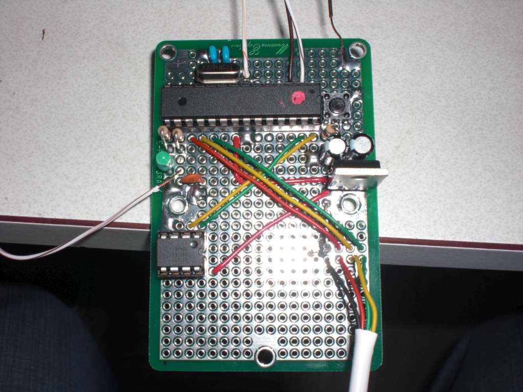
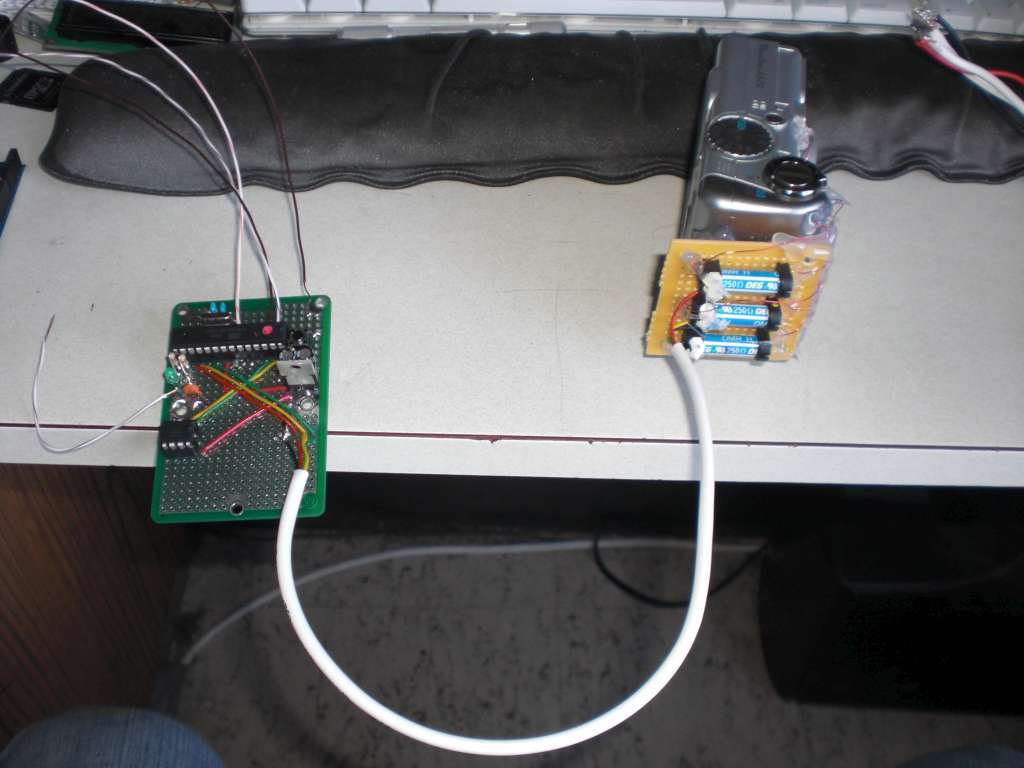
The first addition was a microprocessor. Specifically an arduino. I chose this because it requires a minimal amount of circuitry to run an arduino (Essentially, a few capacitors, a voltage regulator, and a timing crystal). It also, while having minimal requirements, also removes the need for a lot of other circuitry and gives us more options, like digital communications, and timing functions, etc.
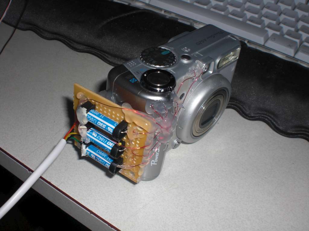
The second addition came in the form of a digital camera. The group decided that we wanted to try and put a cheap digital camera on the flight. I think it could lead to some really cool pictures if it works out properly. I’m using the arduino microprocessor to handle turning the camera on, waiting an appropriate amount of time, focus the camera, wait an appropriate amount of time, and then take the picture before shutting the camera off again. I’m planning on setting up a 5 minute delay for camera photos, that way if the camera survives the whole flight, I’ll be able to get photos from the ascent AND the descent.
Third, the telemetry provided by the people who run the class is rather, let’s say, sad. The class was designed for people to start from no electronics experience to create said project. So their telemetry is extremely basic, and slow. If I were to use their telemetry, I would get one data point every three minutes. Rather abysmal, and one of the people helping to teach the class agreed. He and I talked about the situation, and it logically came up that I’m a ham radio operator, so we worked out how I could run my own telemetry, and get my data, per se, once every ten seconds. This takes advantage of the arduino being able to handle digital communications.
Fourth, and last (so far), is a temperature sensor. The general telemetry system provided by the class has GPS and a temperature sensor for the external environment, and we do have access to that data. However, our processor, camera, circuitry, and likely most importantly our voltage regulator, will be inside a thick styrofoam box. The temperature sensor is for me to see how well the foam insulates the components from the outside. Also considering that the voltage regulator will be getting warm, as the Ozone sensor will draw approximately a watt of power. I am curious as to how the temperature will vary inside and outside the box.
Well, that’s all I’ve really got on the subject for now. We’re flying the thing in two weeks, so I’m sure I’ll have more to talk about it then, along with (hopefully) some really cool pictures. In the meantime, to satisfy the photos lust, here’s some of the control board, and the camera.