After a recent conversation with a friend regarding some datacenter equipment that had only a single power supply, I was curious about building a simple Automatic Transfer Switch (ATS) that would accept two separate AC inputs, and provide a redundant output.
The simple version of this can be accomplished with a single DPDT relay with a 120V AC coil. Connecting the hot and neutral from the primary input to the normally-open connections, the secondary input to the normally-closed connections, with the common connection feeding to the output. Wire the coil in parallel to the primary input so it will activate the relay and connect the primary input to the output. When the primary fails, the relay deactivates and connects the secondary input to the output.
I tried this simple method to begin with, but found that the particular relay I chose did not switch fast enough (despite the specification sheet claiming it should).
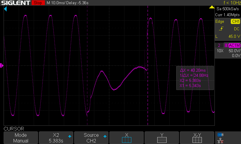
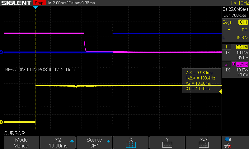
To speak to the speed requirements, computer power supplies are designed to survive a loss of input power for around 16 milliseconds while keeping the system powered, usually called the “hold-up time.” This 16 millisecond timeframe roughly aligns with one cycle of 60Hz power. The oscilloscope capture here shows the time between the cursor where power was lost to the time it switches to the backup is roughly 40 milliseconds, and is far too slow to be effective for most computer equipment.
After this finding I started looking for references in Uninterruptible Power Supplies, as these devices also have to switch power sources in this time frame, as well as reaching out to the manufacturer of the AC relay as to how to achieve the switching times provided in the specifications. The manufacturer responded that the model I had is not capable of meeting the specifications and the spec is based on a model with a 24V DC coil. Similarly the UPS device I looked at used 24V DC coil relays.
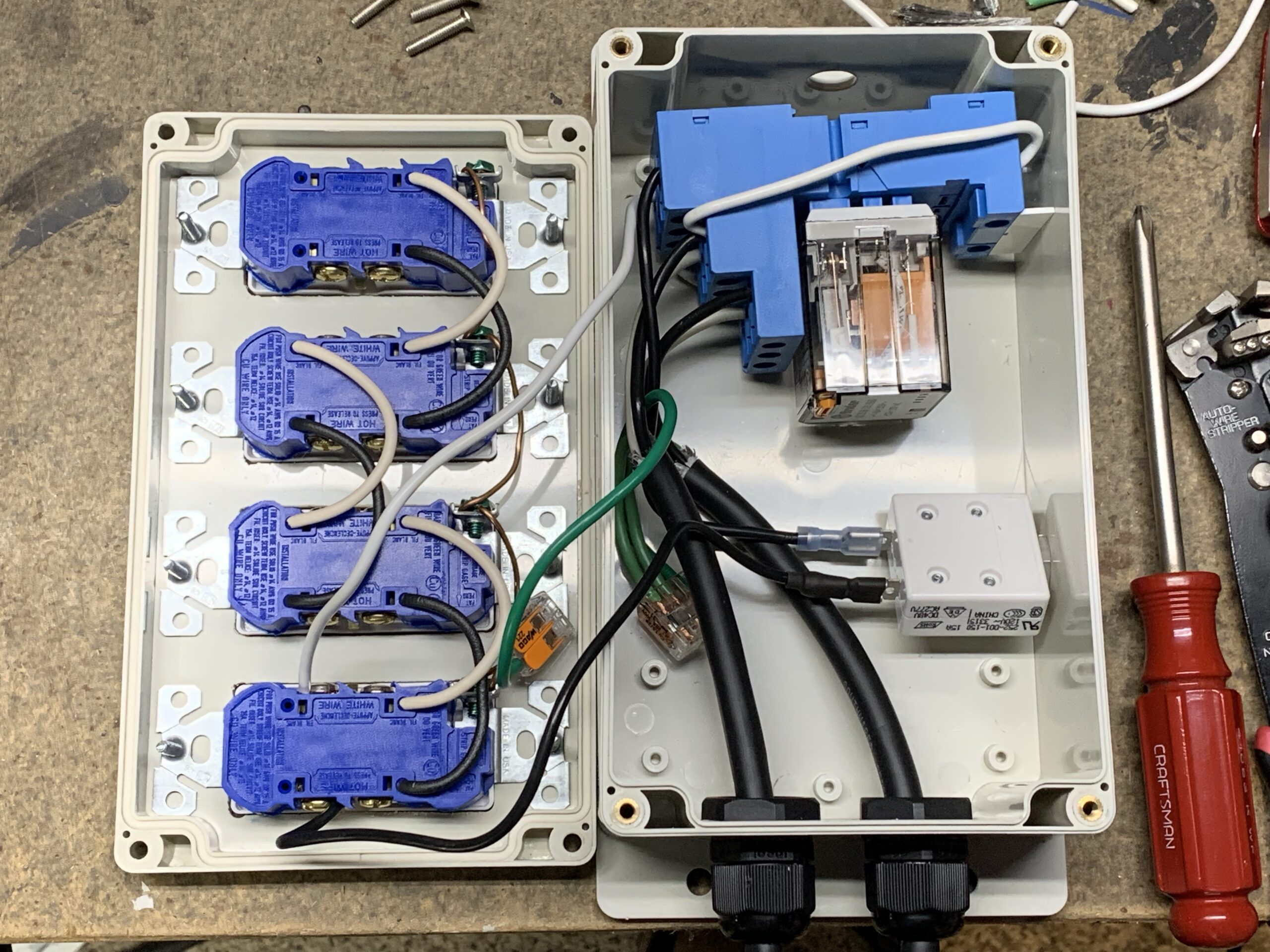
Using 24V DC relays complicates the design as it requires a 24V power supply and the electronics to sense the input and trigger the relay. The 24V power supply, sensing circuit, and control for the relays fit on the circuit board along with the input and output connectors, and the relays. In this case, SPDT relays were used, so two relays are required to switch both the hot and neutral lines.


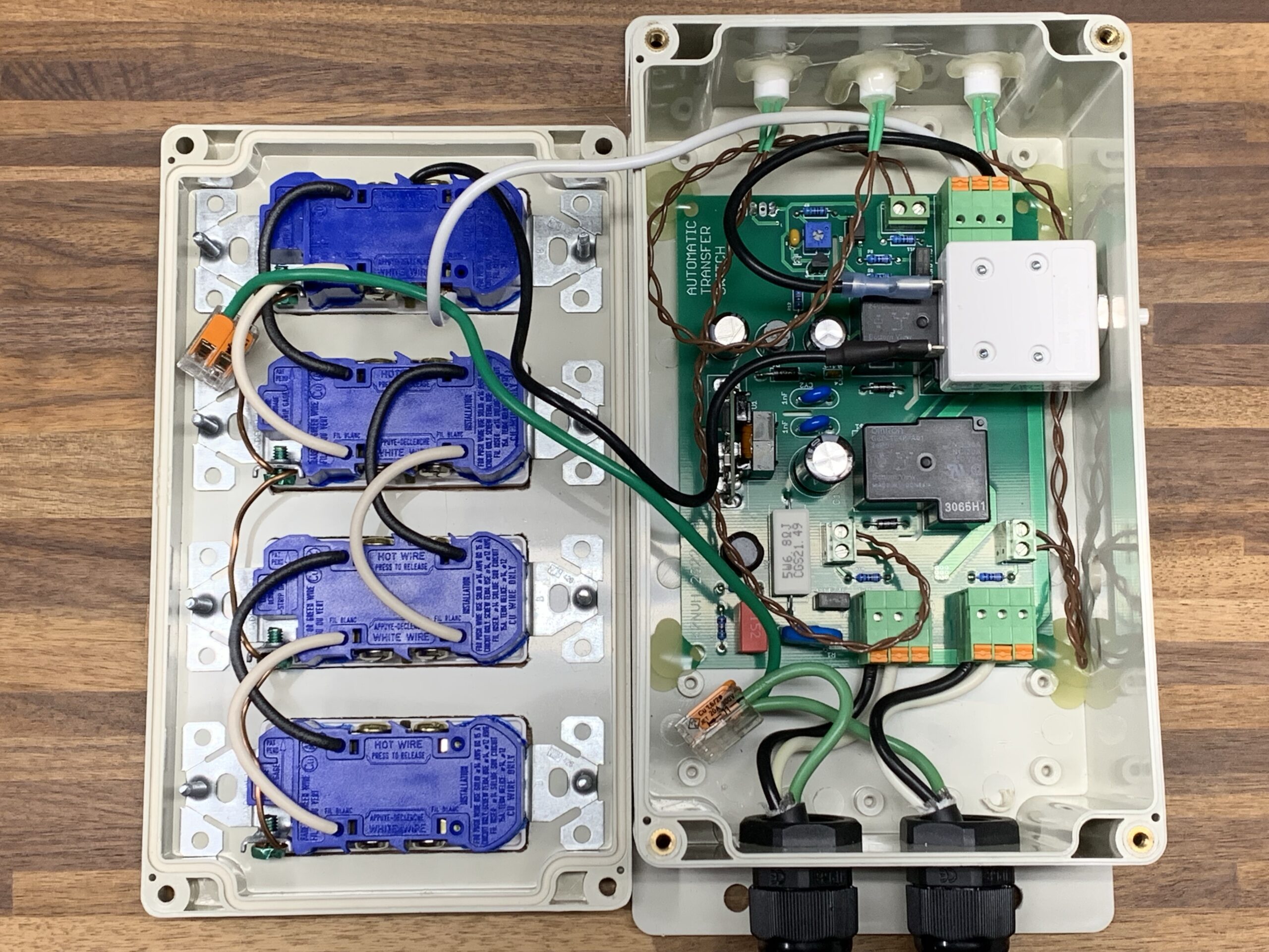
This new design works well and is able to meet the time requirements to switch in less than 16 milliseconds, providing output power from the primary or secondary as available. Here we see the relay switching in roughly 10 milliseconds from the time of the control signal.