Outing for the Arts

Not a terribly long post this time, just thought I’d mention that the gal, some friends, and I went to see The Coats a few nights back. For those who aren’t familiar, they’re a local a capella group of whom I’ve been a fan of for some time. They put on a great show and we really enjoyed the experience. Afterward we hung around for a few and the gal and I got a photo with them. Check it out!

IMG_1112

P.S. This is my 300th post! Woo!

Posted in Art, Life | 1 Comment

Monitor Troubles Part 2

Nearly a year ago, I made a post about some issues I was having with one of my monitors. Well, my other monitor finally decided that it was time for it’s own turn of repair work. Unlike the other monitor, instead of having the display/backlight flicker on and off, this monitor would flicker the image side to side for a moment.

No matter the symptoms, it seems the causes were the same. Replacing the same capacitors as last time appears to have resolved the issue, so now both my monitors have been repaired and perhaps they’ll last me another few years of solid use.

Posted in Electronics, Technology | Leave a comment

Black Rock 2013

As you know, I volunteer with a couple classes at the University of Washington, helping to create telemetry systems for balloons and rockets. The rocketry class in particular generally has two endeavors to launch their rockets. One in the fall over at Mansfield in eastern Washington, and the other at the Black Rock Desert in Nevada.

As mentioned in my last post, I was working on getting a beacon running to handle WSPR and APRS transmissions. I did get both of them working for use down there, but it seems due to a lack of much output power (40 mW) and a very poorly tuned antenna, there weren’t any WSPR spots. However, as the local club has spent a good bit of effort in providing amateur radio services to the area, there are a couple of nice digipeaters that pick up APRS transmissions quite readily, even at only 200mW transmit power.

The beacon I created was set up and running in a tent on the playa for most of the duration of the trip, and after grabbing the data from aprs.fi, I put the data into a spreadsheet program and made up a few nice charts of potentially interesting data.

The first is temperature. The beacon board has a temperature sensor mounted near the final amplifier for the APRS transmitter. This WILL affect the temperature readings somewhat, but the hope is that since readings are taken before turning on the amplifier, and that the transmissions were spaced five minutes apart, that the readings won’t be too terrible. Also as noted above, the board was located in a tent, so the temperatures inside a tent with the sun on it, or a person in it at night, will be much warmer than atmospheric temperature. However, you can still quite clearly see the day night cycle, and changes between the days.

BlackRock2013_Temperature

The next point of potential curiosity is the number of GPS satellites the GPS receiver was tracking at a given point in time. Perhaps this would change with the day as the satellites fly over, or perhaps the receiver might be affected by temperature. However, while there were some changes, this seemed to be random acquisitions and losses of satellite signal rather than regular patterns.

BlackRock2013_Satellites

Lastly, the APRS transmitter section has a small directional coupler built into the board to detect output power. This isn’t calibrated in any way and merely gives raw ADC values. The curiosity here would be if the transmitter chain would provide differing amounts of output power based on environmental temperature. However, while there were some changes, I don’t see a lot of specific change related to the temperature cycle.

BlackRock2013_RF

I don’t have any photos available to share at the moment, but I’ll be meeting with the group soon to have a photo viewing party, and hopefully after that I’ll be able to share some.

Posted in Electronics, Ham Radio, Technology, Weather | Leave a comment

Lat/Long to Grid Square Conversion

In the process of making my WSPR beacon, I wanted the system to both use the time from GPS to sync the transmissions accordingly, but also have the system be portable in that it would generate the needed grid square information from the GPS position.

For this, I needed to write a small function that could handle that conversion for me, and I thought I would share that, at least until I’m ready to share more of the project.

void calculate_grid_square(int lat, int lon){
 if(lon < 0){
   locator[0] = 'A' + ((lon + 180) / 20);
   locator[2] = 9 - ((abs(lon) % 20) / 2);
 }else{
   locator[0] = 'J' + (lon / 20);
   locator[2] = ((lon % 20) / 2);
 }

 if(lat < 0){
   locator[1] = 'A' + ((lat + 90) / 10);
   locator[3] = 9 - (abs(lat) % 10);
 }else{
   locator[1] = 'J' + (lat / 10);
   locator[3] = (lat % 10);
 }
}

This function takes in the integer latitude and longitude coordinates (for example, -122, 47), and will update the values in a globally defined char array named “locator”. You could easily modify to assign the variable as you like.

Also note that this is only a four character locator rather than the full six, as the standard WSPR message only supports a four character locator. You can do a full locator with an extra message, but I’m not going to bother.

Also also note, this was done in the Arduino environment, so if you’re using something else, you may not have, or the names may be different, for functions like abs() (absolute value).

Anyway hope somebody finds it useful.

Posted in Ham Radio, Technology | Leave a comment

15m Low Pass Filter

As mentioned in my last post, I’ve been working on making some coils for a filter I’m making for another project. Anyway, the capacitors I needed came in the mail today, so now it was time to put it together.

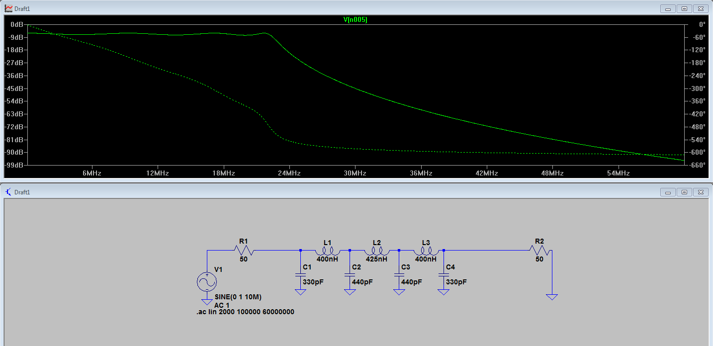
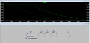
Originally, I started with a simulation in LT-Spice to get my component choice right and see what the expected results would be.

15m_Low_Pass_Filter_LTSpice


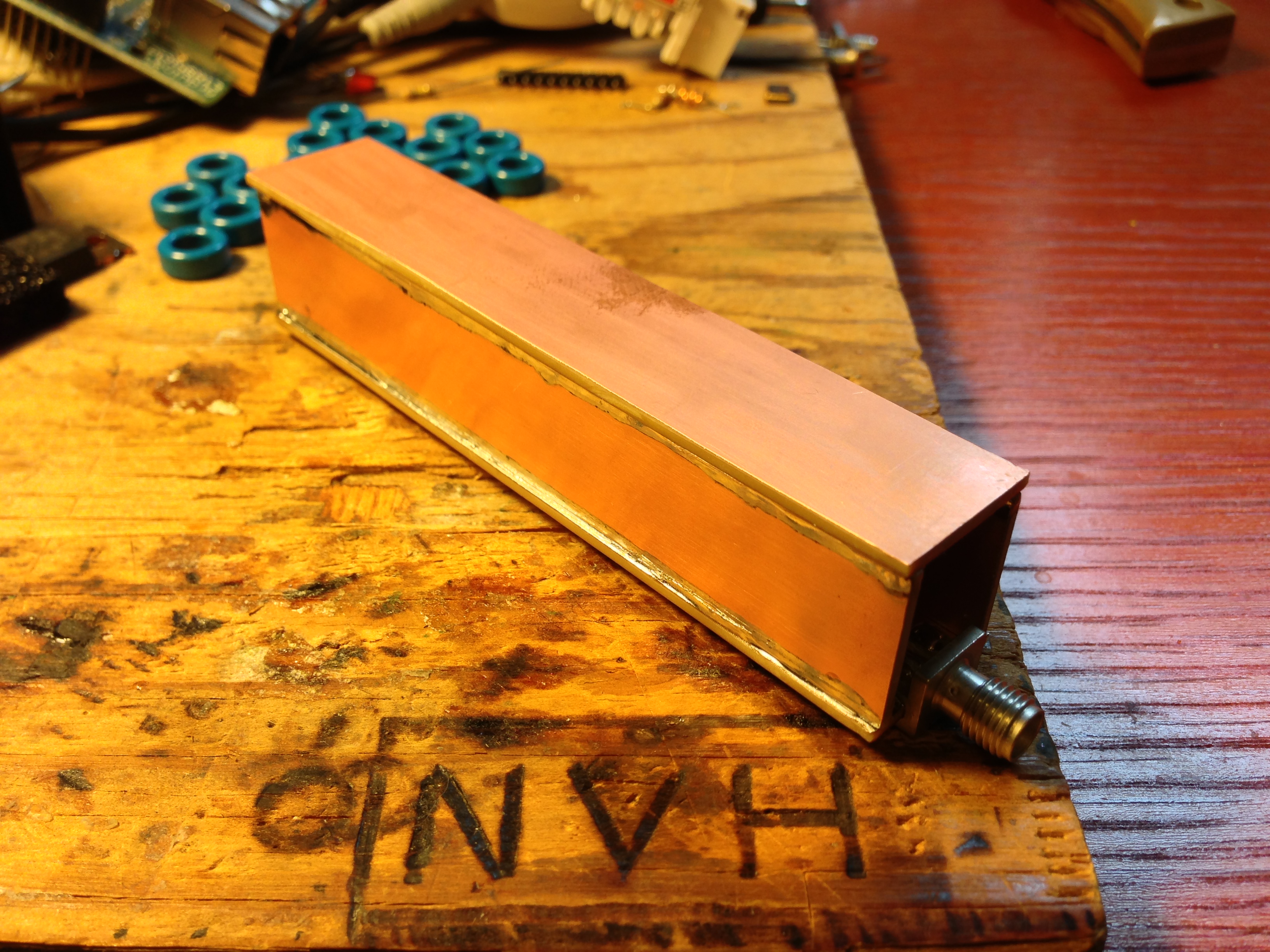
From this, I built my coils and ordered my capacitors. Once they came, I took some copper clad board I had, and used the Dremel to cut the parts. I decided to build the filter into a small box made of PCB. Not because it was necessary to the filter, but this filter will be used in environments where things tend to be handled roughly, and the air coils would not hold up in that environment.

IMG_0966


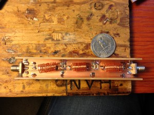
In this photo the lid isn’t on yet, but obviously gives a better view of the capacitors and coils inside. Here it is with the lid on…

IMG_0970


Here you can also get a better look at the soldering along the entire edge of the sides of the box to provide the best grounding at RF.

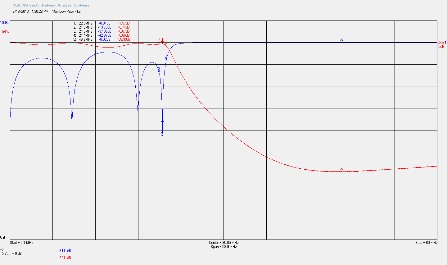
Then came testing the filter with my VNWA. Here’s a capture from the test…

15m_Low_Pass_Filter


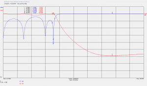
You can see two traces in this graph. The red line shows what signal is allowed through the filter. The first line down from the top is the reference and means all of the signal gets through. Then each division down from that is 10dB down (an order of magnitude).

The blue line is the signal reflected to the transmitter, in this case, reflected signal is output power that won’t get to the antenna, however, we want to reflect our nasty harmonics. So the key is to have a low value (not reflect much) at our transmit frequency (about 21MHz), and reflect as much as possible above that.

So, with this filter, we’re doing a pretty good job of blocking unwanted harmonics. For example, the second harmonic (42MHz) is almost 60dB down. So if our fundamental (desired) output is 1, the second harmonic (unwanted) is approximately 0.000001.

In reality the actual output will be different because it’s not quite 60dB down (more like 57 or so), and that the second harmonic tends to be weaker than the fundamental to begin with. In any case, this filter will make sure my transmissions are well within compliance.

Posted in Electronics, Ham Radio, Technology | 2 Comments