As mentioned in my last post, I’ve been working on making some coils for a filter I’m making for another project. Anyway, the capacitors I needed came in the mail today, so now it was time to put it together.
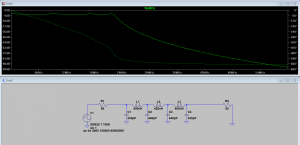
Originally, I started with a simulation in LT-Spice to get my component choice right and see what the expected results would be.
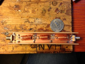
From this, I built my coils and ordered my capacitors. Once they came, I took some copper clad board I had, and used the Dremel to cut the parts. I decided to build the filter into a small box made of PCB. Not because it was necessary to the filter, but this filter will be used in environments where things tend to be handled roughly, and the air coils would not hold up in that environment.
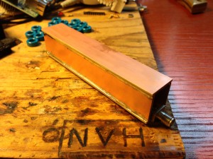
In this photo the lid isn’t on yet, but obviously gives a better view of the capacitors and coils inside. Here it is with the lid on…
Here you can also get a better look at the soldering along the entire edge of the sides of the box to provide the best grounding at RF.
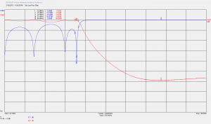
Then came testing the filter with my VNWA. Here’s a capture from the test…
You can see two traces in this graph. The red line shows what signal is allowed through the filter. The first line down from the top is the reference and means all of the signal gets through. Then each division down from that is 10dB down (an order of magnitude).
The blue line is the signal reflected to the transmitter, in this case, reflected signal is output power that won’t get to the antenna, however, we want to reflect our nasty harmonics. So the key is to have a low value (not reflect much) at our transmit frequency (about 21MHz), and reflect as much as possible above that.
So, with this filter, we’re doing a pretty good job of blocking unwanted harmonics. For example, the second harmonic (42MHz) is almost 60dB down. So if our fundamental (desired) output is 1, the second harmonic (unwanted) is approximately 0.000001.
In reality the actual output will be different because it’s not quite 60dB down (more like 57 or so), and that the second harmonic tends to be weaker than the fundamental to begin with. In any case, this filter will make sure my transmissions are well within compliance.


Hello,
My name is Nicole, I try to do an Rf filter .
In my quest I found your web site.
I know few things about how to do this, but I know what has to do this filter.
I have a multilayer coil powered with a DC source.
In close proximity I have a Rf source (another circuit).
From the Radio frequency circuit is induced a current in my DC circuit, in my coil.
I want to do a notch filter, to put it in my circuit to cut 13.56 MHz and its second and third harmonics.
Please can you help me?
i can hardly wait for your answer.
sincerely, Nicole
Hello Nicole,
It sounds like you’ve got a problem with induced frequencies onto a DC line? For the most part, you should be able to work around that with the introduction of ferrite beads and plentiful decoupling capacitors. If you’re really interested in trying a filter design. I don’t believe a notch filter is what you want. Since you want to cover everything above a certain frequency, I would look at using a low pass filter, tuned to block your 13.56MHz signal and the harmonics above it.
Good luck!
Nigel