
So, I’m sure you’ve all heard of the Raspberry Pi, which is a fancy little linux computer that fits in the palm of your hand. It’s certainly not the biggest, fastest, most capable thing out there, but it’s got a lot of appeal with the electronics hobbyist community due to being inexpensive, and having lots of interface options for other electronics.
The Raspberry Pi has admittedly been out for a while now, so it’s nothing new at this point, but I had until now, not had much of a reason to get one. I had Arduino (and similar) boards to do little project things, and I had real x86 computers to do the real computational work.
The impetus came when I was looking for an inexpensive way to set up a camera for a time lapse over the course of something like a week. I needed something that was “reasonably” low power, would run without me needing to fiddle with it much, and would produce decent quality photos.
Unfortunately, nothing I had in terms of a point and shoot camera would fit the bill here, and while something like a GoPro would work, it was looking more expensive and less flexible.
The Raspberry Pi has a camera accessory that takes 5MP stills or video, and is a linux computer when I’m done with the time lapse, and is pretty inexpensive, so, it seemed the choice was made and I ordered one.
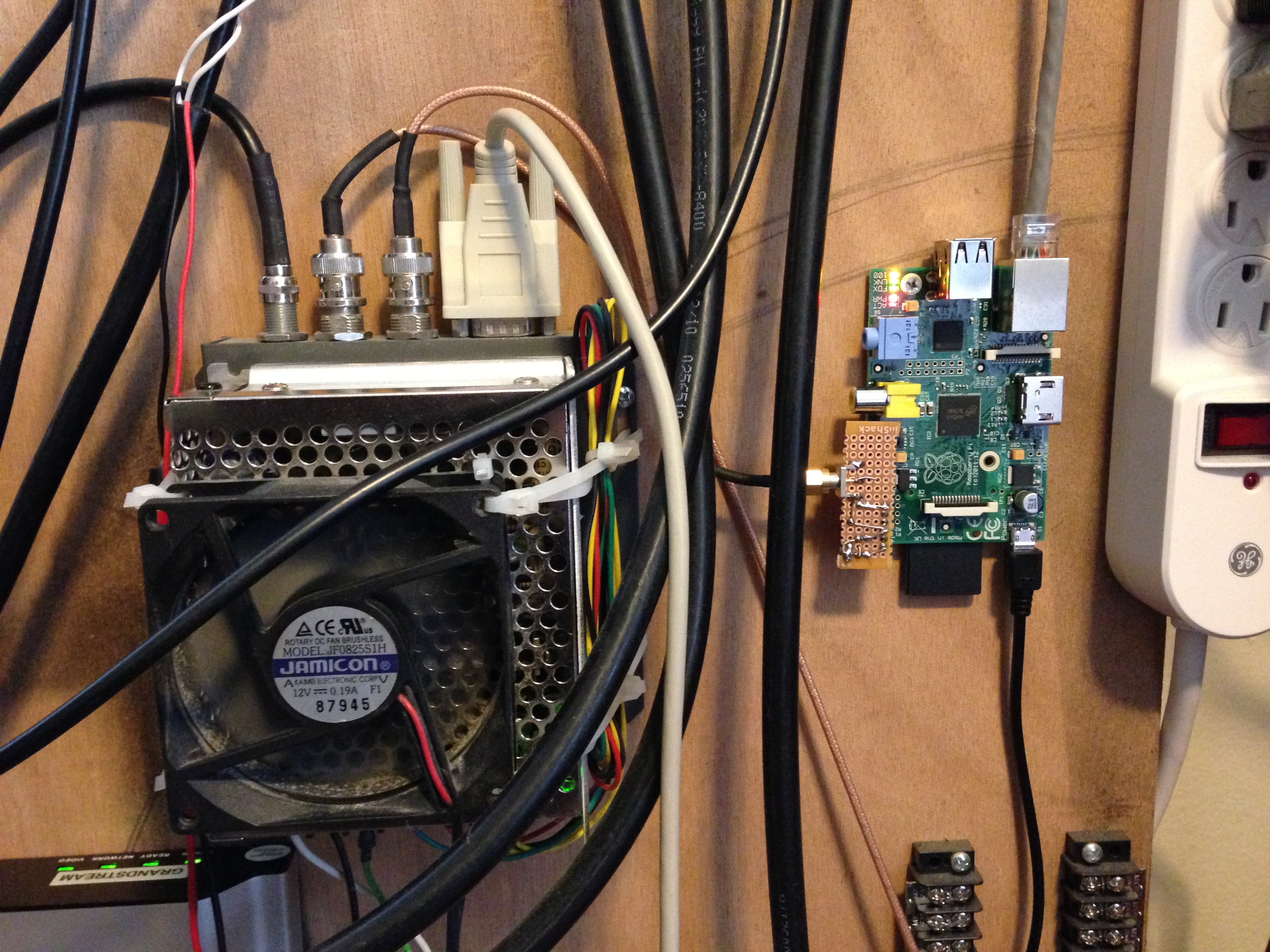
After playing with it for a bit, I realized it was also the perfect excuse, as well as device to build a project I’ve had on my mind for quite a while. A Stratum 1 NTP server.
You see, for a few years now, I’ve had a Trimble Thunderbolt GPS timing receiver. It’s a fancy GPS device that produces very VERY *VERY* accurate timing outputs. I use one of which to clock some of my lab instrumentation to get the best accuracy there, but it has another output, that puts out a pulse once every second, on the second, which is very useful for making an accurate clock.
Through a bit of digging on the intertubez, I found that a few other people had taken Raspberry Pis, or similar small low power boards and used GPS PPS (Pulse Per Second) outputs to create high accuracy Stratum 1 NTP servers. Using a combination of their collective information, I re-compiled the kernel on the Raspberry Pi to support watching a GPIO pin for pulses, and use those pulses to have the kernel discipline the local clock into being as accurate as possible.
After which, it was a simple matter of editing the config file for NTPd and starting it up. BAM! It saw that it had a PPS signal source, grabbed the coarse time from other random NTP servers it found in the ntp.org pool, and then started disciplining the local time with the high accuracy signal.
So, now I have a Stratum 1 time server here at my house, feeding my systems, as well as whomever else decides to use it (time.k7nvh.com).
You can also find the references I used here:
Raspberry Pi Kernel Compilation
Building a Stratum 1 NTP server with a Raspberry Pi
Hi Nigel, I have a Trimble Thunderbolt on the way and I’m going to setup an NTP time server with a raspberrypi. I was glad to run across your blog post here. I’m curious, I see that you have a circuit of sorts in the picture for the PPS input on the GPIO pin. was this a Cap and Diode to stretch the PPS signal length from the Thunderbolt? Or maybe a voltage divider to drop voltage down to 3.3v for the GPIO pin? I’m finding a lot of good info for other GPS based PPS output, but not so much for direct input from the Thunderbolt PPS.
Thanks again for the nice block and picture. 73 de Max NG7M
Hey Max,
Glad you’ve found it interesting. The circuit is pretty simple, but yes, you’re right in that I had to do a little bit of stretching and voltage drop since the Thunderbolt PPS output is at 5V. I used a capacitor, resistor divider, and a transistor to accomplish it. Mostly just by fiddling values until the signal was down at 3.3V on the oscilloscope.
Nigel
This is great! Could you provide a draft schematic? I plan to do this myself too! Thanks in advance.