So, for a bit of an update on my transmitter project. I’ve made a few minor wire fixes to the board. Mostly just adjusting what outputs on the ATmega are connected to what.
Most of the work involved has been software. I’ve got a ham friend working with the same PLL chip, and I’ve used his code as an excellent reference on interfacing with the PLL.
I’ve also got an existing APRS implementation, however it was blocking code, so I’ve been spending a lot of time rewriting my APRS implementation to be interrupt driven. Hopefully I’ll end up with a lot cleaner APRS generation.
I’ve also redone the filters. The original filters I had designed had been, to put it lightly, awful. They were mostly an RF absorber. After replacing the filters with something reasonable, I’m measuring about a 1/4W CW output. Maybe just a little higher.
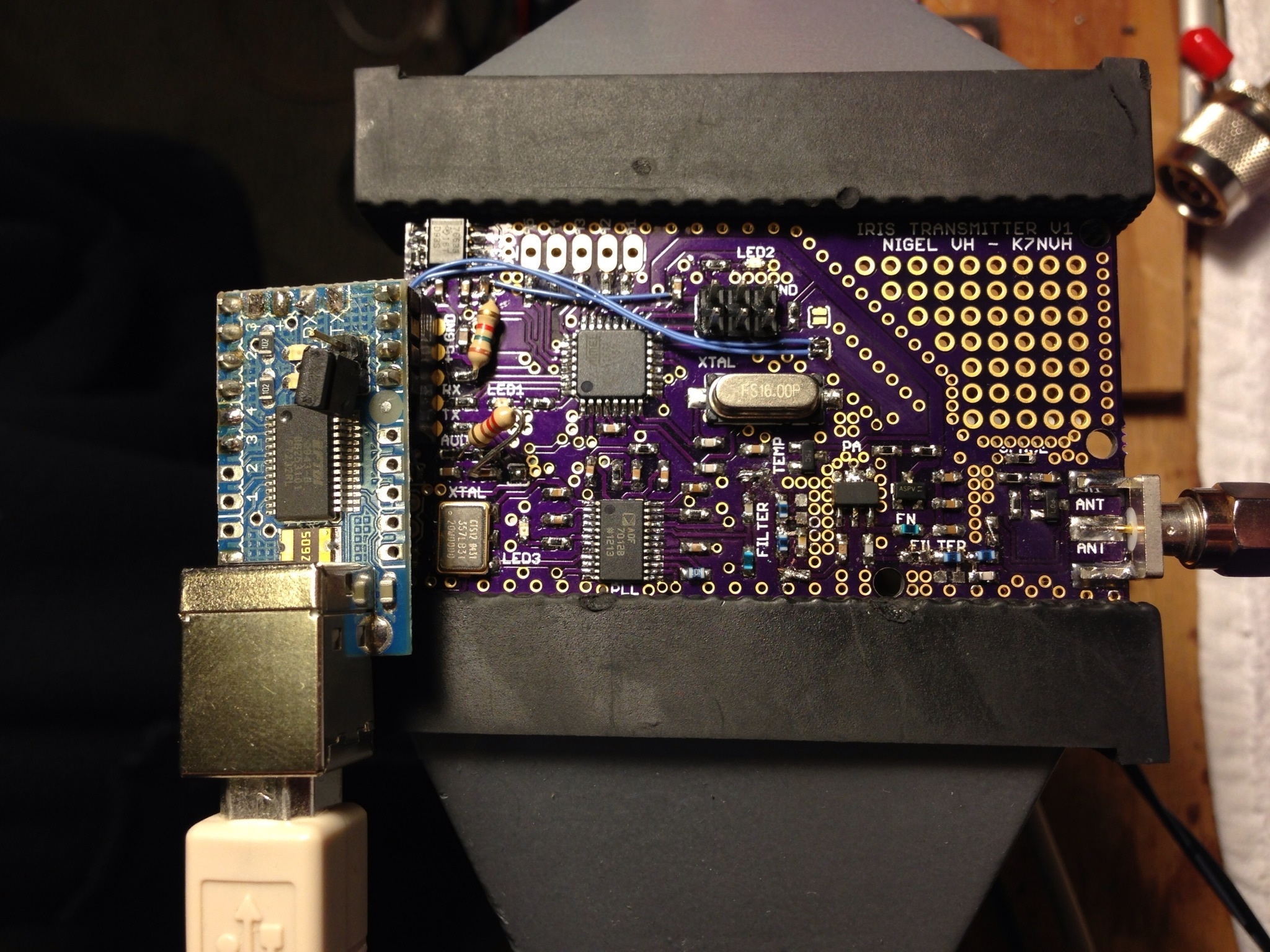
The processor is an ATmega328P, which talks to a ADF7012 PLL synthesizer to generate the 144.39MHz signal. The signal is modulated by means of a VCXO acting as the reference for the PLL. Total output power was brought up by means of an RF FET amplifier stage, to a level of approximately 250-300mW. The board required a power supply of a regulated 5V input, and included a linear regulator onboard to supply 3.3V to the ADF7012.
Overall, so far I’m impressed with the results. Hopefully soon i’ll have APRS working totally, and I can start transmitting. Who knows, maybe I’ll show up on the map in your neighborhood.