This is a project I’ve been working on for a while, and have refrained from posting about it for lack of specifics. Well now I have specifics. The boards are in and I’ve assembled my first home made transmitter!
I’ve always thought it would be cool to make my own transmitter, but due to either a lack of time, or a thought that I didn’t know enough about RF, I hadn’t gotten around to it. I ended up stumbling across a very similar design by one of the guys on an IRC channel I frequent, and began an email correspondence with him. After some talking, I decided to try my hand at it.
The goal was to create a low power transmitter, that is compact enough to use on a rocket or high altitude balloon flight, that is frequency agile within an amateur radio band and that, with component choices during buildup, is capable of operation on any of the 2m/1.25m/70cm/33cm amateur radio bands.
As I just got the boards and assembled one last night, I don’t have the software to actually run the transmitter done, however, I’ve loaded a few test programs to it, and have confirmed that the processor is running, the VCXO is running, the regulator for the RF transmitter is running and the PA temperature sensor is working.
In summary, what I haven’t tested so far is the PLL, the PA, and the RF power detection circuit. (Most of what actually makes it a transmitter…)
So, while you’ll have to wait on specifics for power output (I’m hoping for about 1/4W) and whatnot else RF characteristics, I do have photos of the boards.
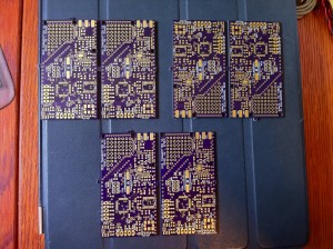
The above is how the boards came to me. For this order, I used a new fab place that does boards cheaper than many others. Go ahead and look them up at oshpark.com. For the size of these boards, it was about $40 for the six.
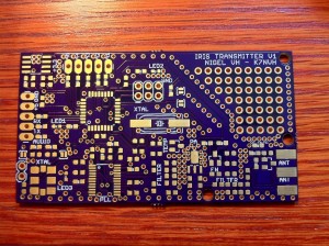
Here’s a closeup of just one by itself. I’m pretty pleased with this fab place. Purple boards and gold pads. Classy.
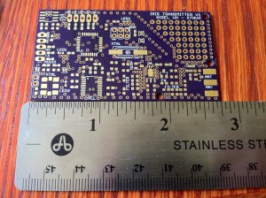
Here’s another shot with a ruler. The boards are 2.75″ x 1.5″.
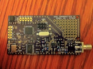
Here’s a closeup with everything on the board populated. Minus the five pin headers on the top and left. Though, those aren’t strictly necessary. Wires could be soldered there instead of headers.
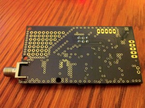
Here’s a shot of the bottom side of the board for good measure. The fab place will do bottom silkscreen for no extra charge, but since I wasn’t placing any components on the bottom, I didn’t bother with any silkscreen on the bottom.
Enjoy the photos, and hopefully I’ll have more progress with it soon!

