LED Matrix

You’ve seen this little LED matrix on here a few times before, I’ve used it in a few projects, and have always had it on it’s own with some wires running to it. I got tired of doing that, so I’ve created an arduino board, and attached the matrix to it, then made a stand for the whole thing. That way, I can program the arduino to handle whatever it is I want the thing to display, as well as talk to it over serial. Really, what it comes down to is that it makes things a little easier, and I thought it would look cool. Here’s the customary media to show it off.

CIMG0139

Posted in Technology | Leave a comment

Nerf Dart Gun

Here at the office we have fairly regular Nerf battles, in which everyone would grab their gun, and a handful of darts and start trying to shoot each other while hiding behind our monitors.

For a long time, I haven’t had a nerf gun, so I’ve just been hand throwing the darts. Though, I’ve gotten pretty good at it, I wanted something better. Naturally, this involved a trip to home depot.

A few hours later, I had a custom made, high power Nerf Dart gun. Here’s the pictures.

As you can guess by the bicycle tire pump next to it, it’s powered by compressed air. The steel cylinder at the rear holds the compressed air, it goes through the valve with the red trigger, out to the copper tubing that fits inside the shaft of the Nerf Dart.

Generally I can get about eight good shots out of my gun before it needs to be pumped up again. The shot quality varies quite a bit within those eight though. The first two or three are really really powerful, shooting extremely fast, and flying with minimal altitude drop. With the rest, the power drops off, and they begin to drop more as they fly.

Posted in Life, Random | Leave a comment

Huge Ass Power Supply

Well, I’ve finally done it. I’ve created a power supply that could destroy the universe as we know it. Well, not THAT powerful, but plenty large.

It’s primary (expensive) components came from a big pile of free stuff the girly pointed out to me. Throw in a few bits from RadioShack, SparkFun, and Maxim-IC and you’ve got a big nasty humming box.

As you can see by the image, it’s not quite all the way put together, but electrically it is functional. You can see in the above image the four large power capacitors (Three for cleaning and storing the rectified AC, and one for the 13.8V output stage). Behind the three in a row, you can see a tiny bit of the three transformers that step the 120V input down to 30V.

The 30V rectified output from the transformers is fed into the power board, where it is regulated down to 13.8V via the large power transistors on the right of the second image. These are controlled via the various parts best seen in the first image.

Then a microprocessor controls the relay that turns on and off output power so that the supply can shut itself off in case of short circuit, overheat, voltage fluctuations, or any other reason I choose. Here’s the logic board.

It uses an arduino processor connected to a Maxim-IC MAX127 which measures the voltages around the power supply, and also allows me to sense current flow via a resistor shunt.

The arduino also connects to these temperature sensors which are DS1621 sensors.

All of this information can be read out via this display, and controlled by the associated switches.

By the way, for those who are interested, I expect the power supply to be able to put out power in excess of 20 amps. However, this is of yet untested. One of these days I’ll connect a big ass load to it and see what it does.

Posted in Random, Technology | 5 Comments

LED Display

We’re all familiar with the classic old “7 Segment” displays. You know, the little red numbers you could get from radio shack. Anyway, I had a few extra parts laying around, and had an idea for what I could use them for, so I made a little display using four of them. For those who just want the pictures, here they are. For those who want the details, read on.

Alright, now for the nitty gritty. In reality though, it’s not really that gritty.

I got some free samples from Maxim-IC a while back, and among them were two MAX6956 I/O Port Expander / LED Driver chips. These two chips can be programmed with a unique address, so that I can use the same two wires from the arduino to control both of them. Via this, I can control 20 pins on each chip. (40 total between the two.)

They also have a built in current limiting mode for driving LEDs so you don’t burn them out. This is set via the external resistor seen in some of the pictures.

I programmed the arduino to keep time, and then turn on and off the appropriate pins to create the numbers on the segments. Pretty simple really. It was actually a lot harder getting all of those little wires through the holes in the back board all at the same time.

The whole assembly is run by four conductor phone line which carries the power lines, and the two data lines.

Really though, the clock function wasn’t my plan for this little project. It was just a test to make sure it worked, and enjoy my handiwork while I finished my other project. The goal is to have it be a voltage display on a power supply I’m building. I won’t spoil the next blog post which should be about that. (Theoretically I’m close to finishing it.) However, it’s safe to talk a little bit about it.

I got most the parts for it from the same free stuff pile that I got these little displays from, and the same one I got the EL Display from. (Yes, he had a lot of stuff)(Also, for credit where credit is due, the girly pointed it out to me on craigslist, and tolerates my massive piles of electronics crap. Thanks hon!)

Anyway, the last I’ll say about it, is that it’s massive, both physically and electrically. So it goes without saying that I’m excited to see the results.

Posted in Random, Technology | Leave a comment

EL VGA Display

Well, once again I come to you bearing news of nerdy things. Pretty damn nerdy things. However, you can’t blame me, blame my girl. She found the big pile of really cool free electronics stuff on Craigslist. Really, do you blame the dog for eating food left on the floor? No, you dont, and I couldn’t help myself.

Anyway, she found a free listing on Craigslist of a guy who had a ton of old electronics stuff. So I went out there yesterday and grabbed a big boxful of it. To be honest, I feel kinda bad taking it for free, because this was a steal. I don’t mean like you took a penny candy from the corner store kind of steal.

Granted that some of the stuff is old, and some is a bit damaged, but there is still easily several hundred dollars worth of bits in that box, and when it was new, and pristine, I’d place the total somewhere near a grand.

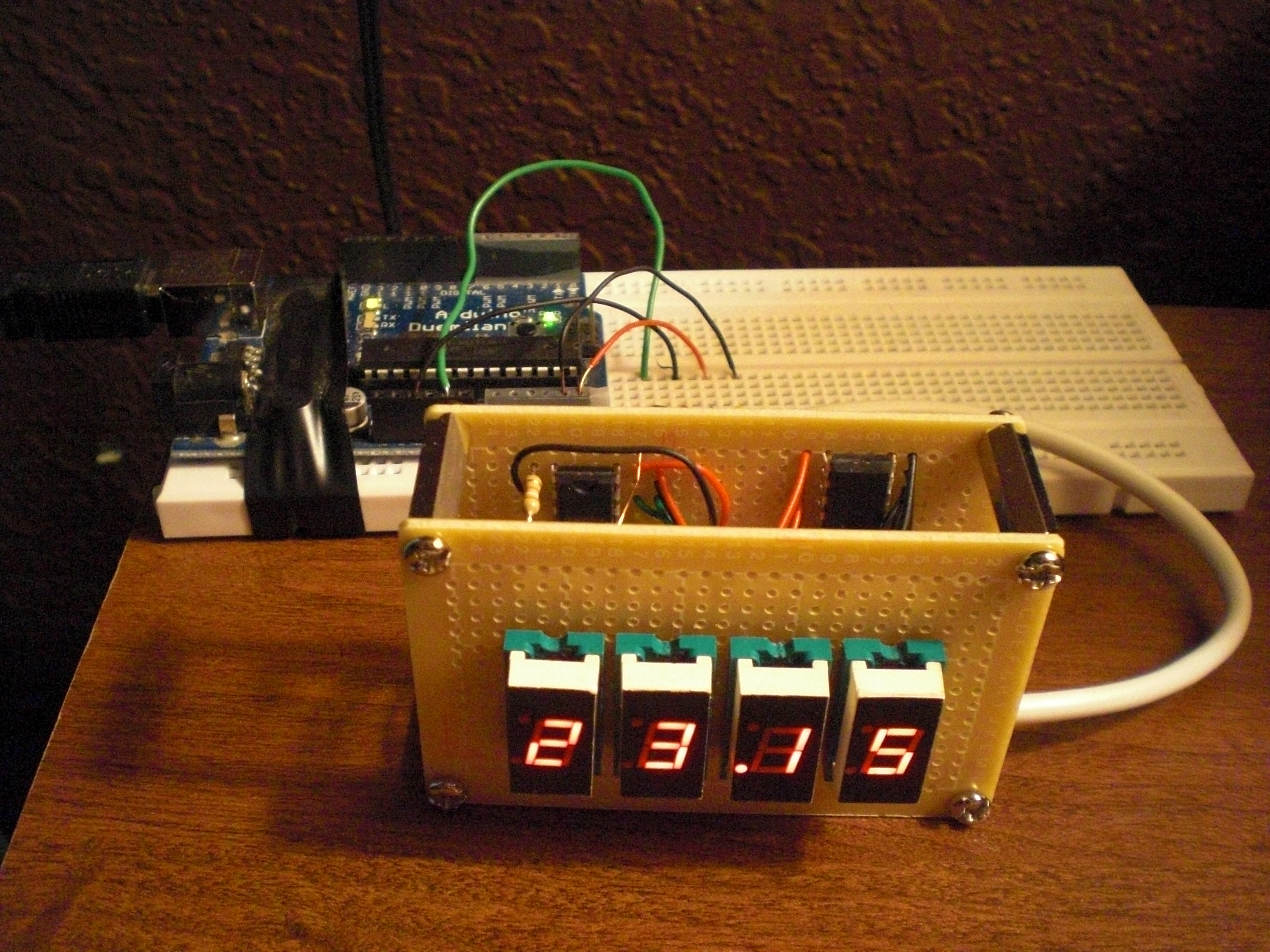
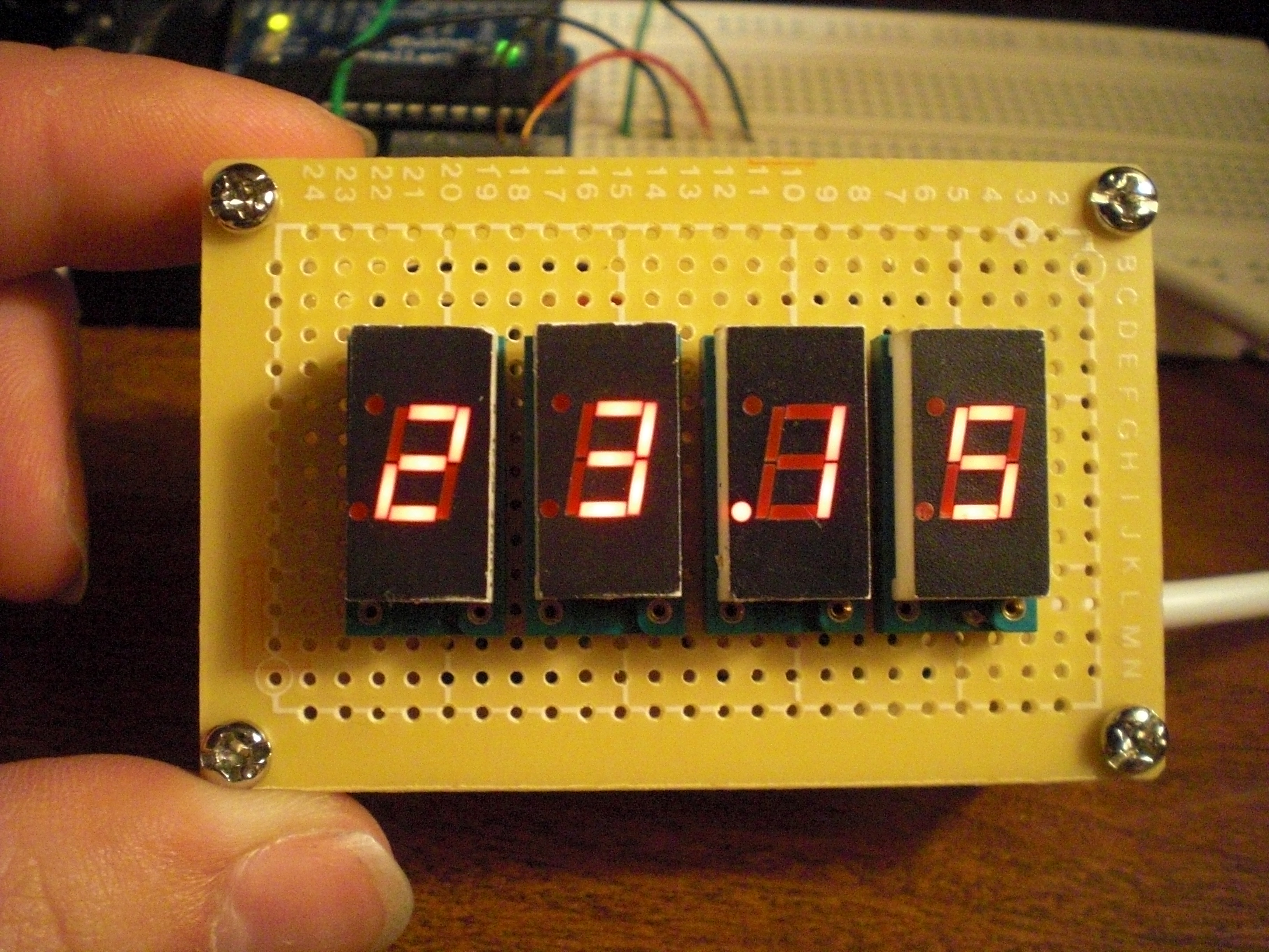
I managed to come away with a bunch of stuff ranging from a box full of capacitors/resistors/etc, to huge 53 Farad capacitors, to a bunch of wire, to a few lcd panels. (Not the kind you connect to your computer.) I’ll talk about the rest of the stuff later, the thing I’m gonna talk about now is one of the lcd panels I got.

It’s a EL (Electro-Luminescent) panel. Which means that unlike an LCD which creates dark/light spots that a backlight shines through, in an EL panel each pixel actually emits it’s own light. However it’s not the same as an LED panel which uses different technologies to accomplish the same thing as the EL panel.

Unfortunately (for me), they designed this panel to be like a VGA display, in that you must provide a new image for the panel somewhere in the range of 60 times a second (60 Hz sound familiar? That’s because it is!). Being 640 pixels wide, and 480 pixels tall, that means that I need to write 307,200 pixels in a 60th of a second, or 18,432,000 pixels per second. That’s REALLY fast.

If you go too slow, then you just get a line that scrolls down the screen. I found that out after writing some very basic code to turn every pixel of the screen on for my arduino. It was a little slow. Then after doing some research, I found that the digitalWrite functions I was using to generate the digital communications take quite a bit of time to actually change the state of the output pin. I found a way that writes directly to the hardware port register which happens a lot faster. After optimizing code, I’ve got it up to about 68Hz. However, I don’t have anything fancy displaying, so we’ll see what I can push out of it with that extra 8 Hz.

Here’s some pictures, and a video displaying it actually working. (Alternating lighting up half the screen.)

CIMG0178

Posted in Random, Technology | Leave a comment